Eureka AIR delivers breakthrough ideas for toughest innovation challenges, trusted by R&D personnel around the world.

Vacuum-assisted foaming method and apparatus for moulding insulation of refrigeration containers

Inactive Publication Date: 2011-10-27
CANNON ERGOS
View PDF1 Cites 70 Cited by
  • Summary
  • Abstract
  • Description
  • Claims
  • Application Information

AI Technical Summary

Benefits of technology

[0014]A general object of the invention is to provide a method and an apparatus for vacuum assisted foaming, that is for foaming under vacuum condition and moulding an insulation of polyurethane material into hollow walls of containers for food such as refrigerator cabinets, freezers and similar refrigeration containers, by which it is possible to considerably reduce the volume of air to be sucked to generate vacuum, obtaining a considerable saving in energy, and reduction of the working time.
[0015]A further object of the invention is to provide a new solution for a foaming apparatus of comparatively reduced dimensions and cost, which can be used both for newly designed foaming apparatus, and for retrofitting an existing conventional foaming apparatus, improving their performance.
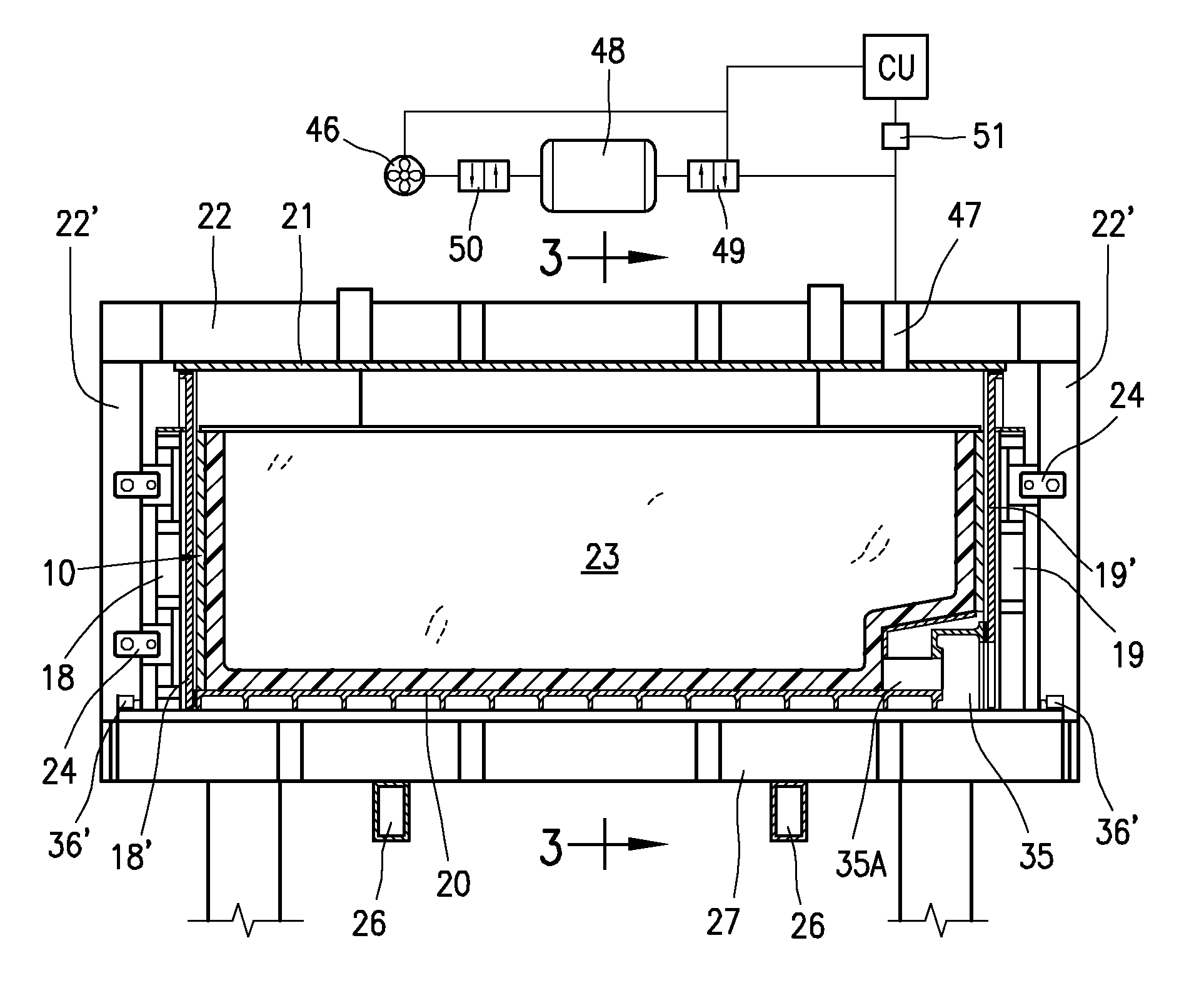
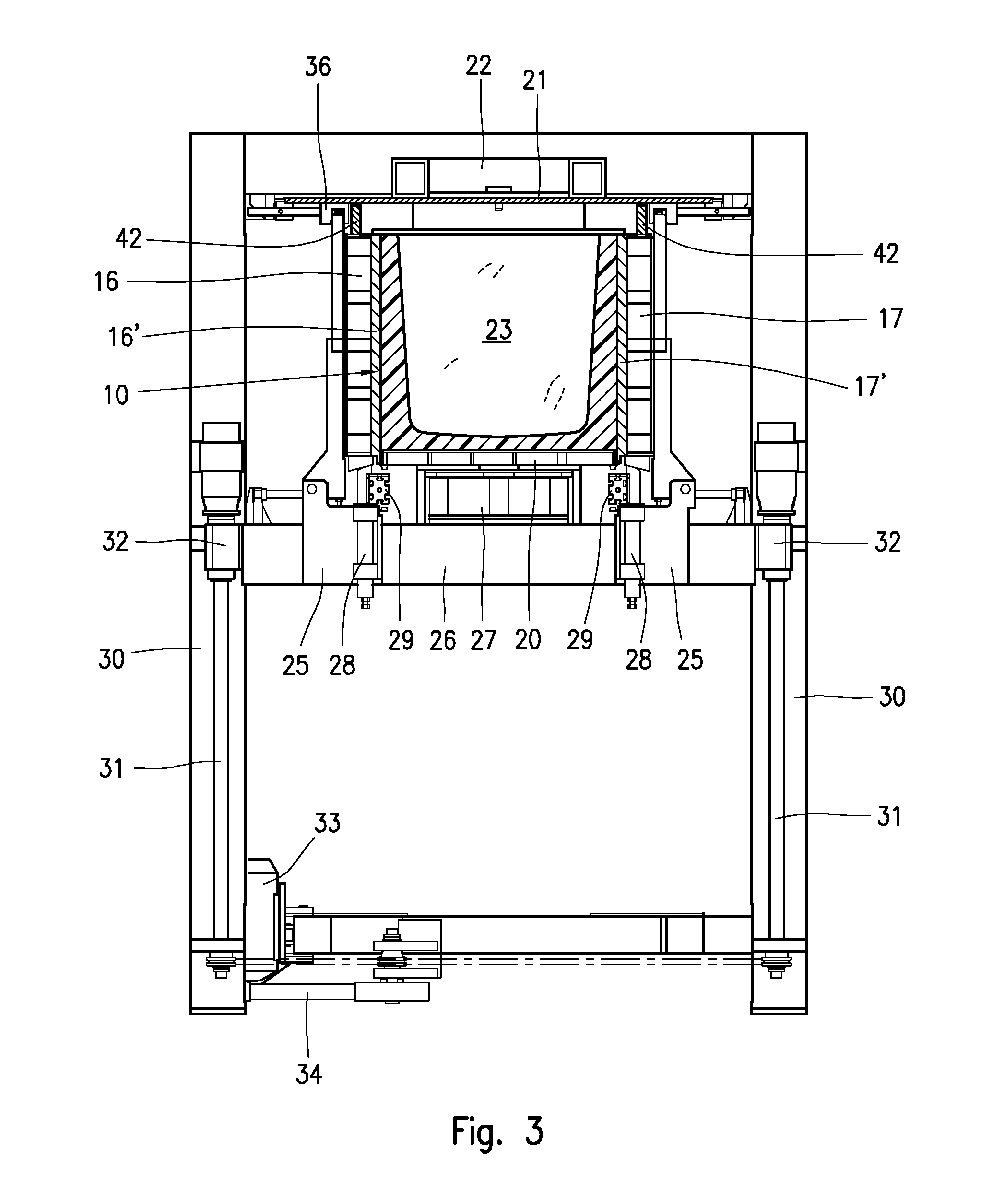
[0018]In general terms, the problem has been solved by enclosing a refrigeration container having peripheral hollow walls, into a foaming cell of extremely reduced space, basically corresponding to the air volume of the refrigeration container to be foamed, or slightly higher; in this way, it is possible to considerably reduce the volume of air to be sucked for generation of a required vacuum degree, with consequent energy saving, reducing at the same time the dimensions and cost of the foaming apparatus compared to a foaming apparatus of conventional type.

Problems solved by technology

One of the greatest problems involved by a foaming apparatus of known type, relates to the “model change”, i.e. a problem consequent upon passing from moulding the insulation of one type of refrigeration container to another one having a different shape and / or dimensions; at each model change, the plug member must be removed and replaced with another one conformed to the cavity of the new refrigeration container to be foamed, after which the resetting of the entire apparatus must be performed; this all requires special equipment, the presence of several experienced operators and lengthy intervention times, with consequent limitation of productivity of the entire processing plant.
Although a foaming apparatus of this type has proved to be suitable for the contemplated use, several limits came to light during tests, in terms both of mechanical design of the apparatus and foaming process.
Since the volume of air to be sucked and exhausted from the vacuum chamber is comparatively high in respect to the volume of air to be exhausted from the hollow walls of the container, this solution, besides requiring a sturdy structure and a high cost, involves also a high consumption of energy necessary to suck a large quantity of air to reach a required vacuum condition or vacuum degree.
The large volume of air to be sucked to reach a desired vacuum condition, leads in turn to an undesirable increase in the processing time and, consequently, the entire operative cycle.
There are currently no solutions to these problems; therefore a need to further improve this technology still exists.

Method used


Image

  • Vacuum-assisted foaming method and apparatus for moulding insulation of refrigeration containers
  • Vacuum-assisted foaming method and apparatus for moulding insulation of refrigeration containers
  • Vacuum-assisted foaming method and apparatus for moulding insulation of refrigeration containers

Examples


Embodiment Construction

[0033]The invention will be now explained making reference to the foaming under vacuum condition of a refrigeration container consisting of the cabinet for a refrigerator, being understood that what will be described for a refrigerator cabinet, will be valid also for any type of refrigeration container of the type previously referred to.

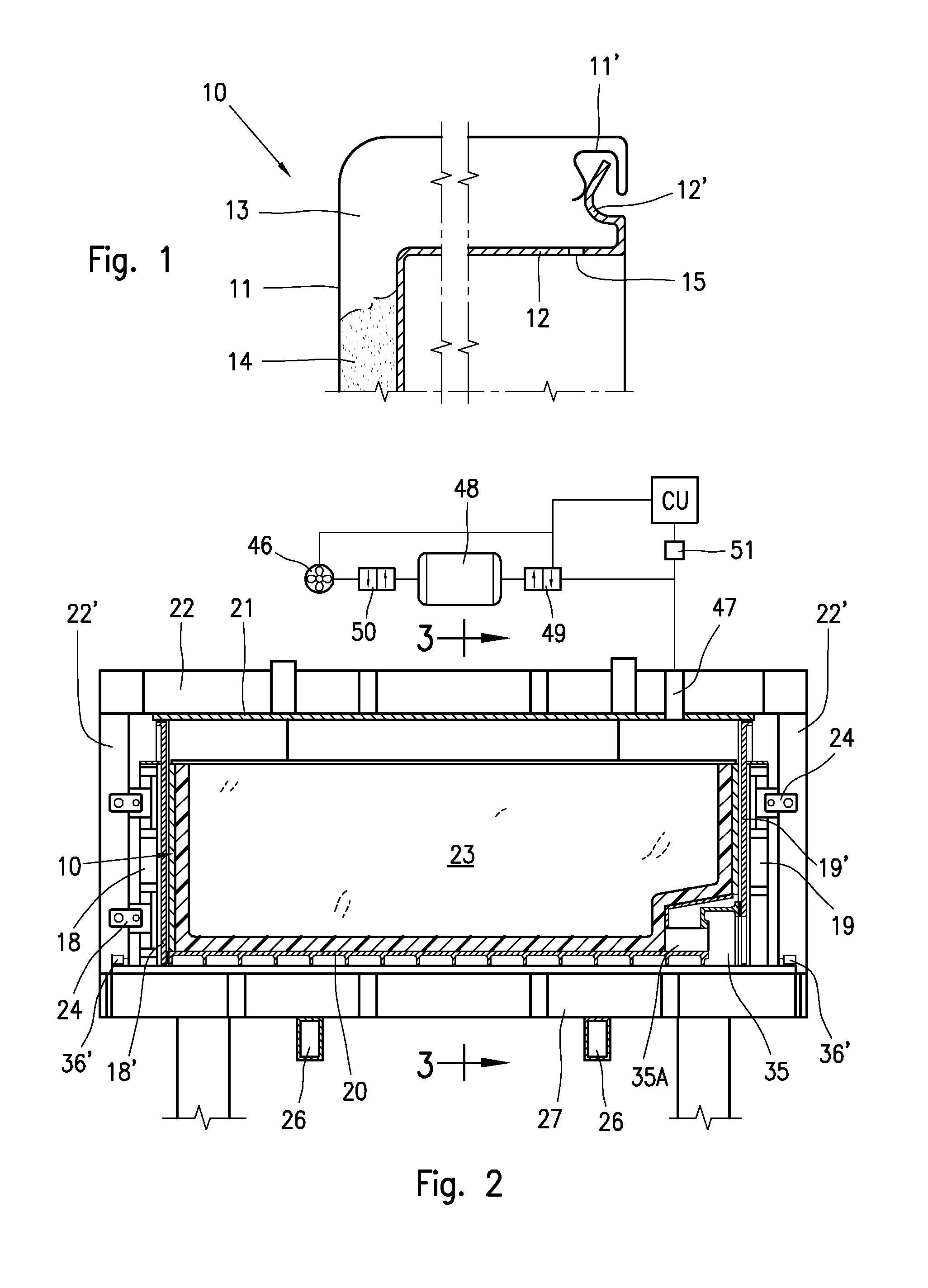
[0034]FIG. 1 shows, by way of example, the upper part of a refrigerator cabinet 10, comprising an external metal shell 11, and an internal shell 12 obtained for example by thermoforming sheets of plastic material, or by shaping metal sheets.

[0035]The two shells 11 and 12, as shown in the detail of FIG. 1, have their peripheral edges 11′ and 12′ duly shaped and engaged with each other, to maintain the shells 11 e 12 in an assembled condition in which they define the hollow walls 13 of the refrigerator cabinet 10. In a manner per se known by a suitable foaming process, a metered quantity of a liquid polyurethane mixture is injected into the hollow wall...


PUM

PropertyMeasurementUnit
Pressureaaaaaaaaaa
Vacuumaaaaaaaaaa
Compressibilityaaaaaaaaaa

Abstract

A method and an apparatus for foaming a refrigeration container (10) for foodstuffs, with a reactive polyurethane mixture injected under vacuum condition into hollow peripheral walls of the refrigeration container (10) enclosed in a foaming cell. The foaming cell includes a bottom table (20) for supporting the refrigeration container (10), side shore panels (16, 17, 18, 19) and an internal shore plug (23) fastened to a closure lid (21), conformed to rest against outer and inner surfaces of the peripheral walls of the refrigeration container (10), and sealing gaskets (40, 43, 44, 45) between contact surfaces of the side shore panels (16, 17, 18, 19), the bottom table (20) and the closure lid (21), to provide an air-tight closable foaming cell connectable to a vacuum source (48).

Description

BACKGROUND OF THE INVENTION[0001]The invention refers to a foaming method and an apparatus for moulding under vacuum condition insulations of refrigeration containers, such as cabinets for home and industrial refrigerator cabinets, freezers, refrigerated display cases and refrigerated counters for foodstuffs, according to which a foamable polyurethane mixture is injected under vacuum condition into hollow walls of a refrigeration container enclosed into a foaming cell of extremely reduced space.STATE OF THE ART[0002]A refrigeration container to preserve and / or display foodstuffs, usually comprises outer and inner shells which in an assembled condition define the hollow walls of the container, in which an insulation layer is moulded by injecting a heat insulating and foamable material, such as a reactive polyurethane mixture suitable to foam and expand inside the hollow walls. During the expansion, the polyurethane foam will tend to urge against the inner surfaces of the hollow walls...

Claims


Application Information

Patent Timeline
IPC IPC(8): B29C45/76B29C44/42B29C44/18
CPCB29C44/3403B29C44/428F25D23/064B29K2105/04B29L2031/7622B29K2075/00
Inventor CORRADI, PIERODE ROSSI, CLAUDIO
Owner CANNON ERGOS
Why Eureka
Eureka Blog
Learn More