
System and method for the creation of 3-dimensional images

a technology of 3-dimensional images and creation methods, applied in the field of image processing, can solve problems such as color suppression, eye fatigue, and inability to obtain true color images

Inactive Publication Date: 2011-10-20
BMUSE GRP
View PDF0 Cites 55 Cited by
  • Summary
  • Abstract
  • Description
  • Claims
  • Application Information

AI Technical Summary

Benefits of technology

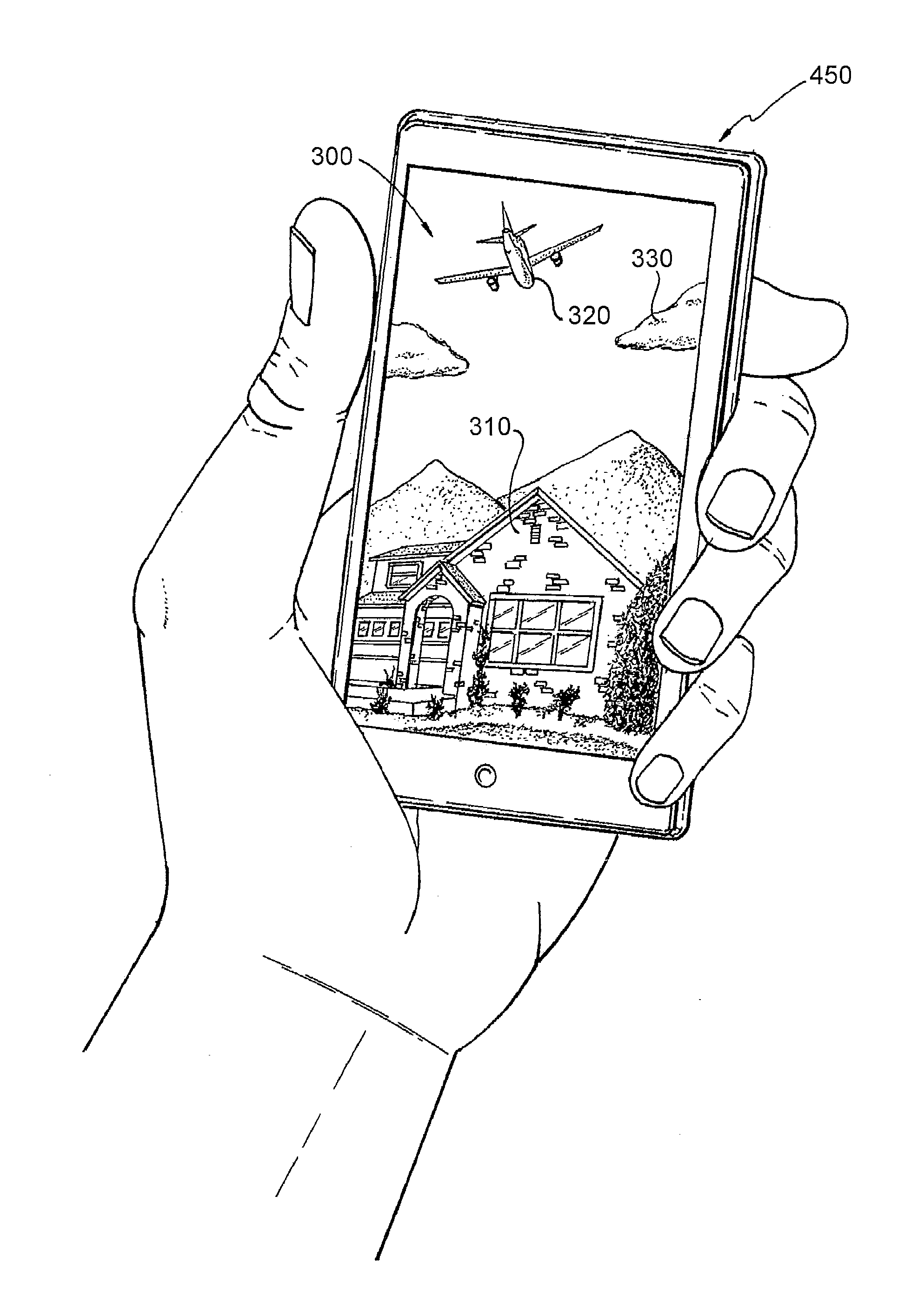
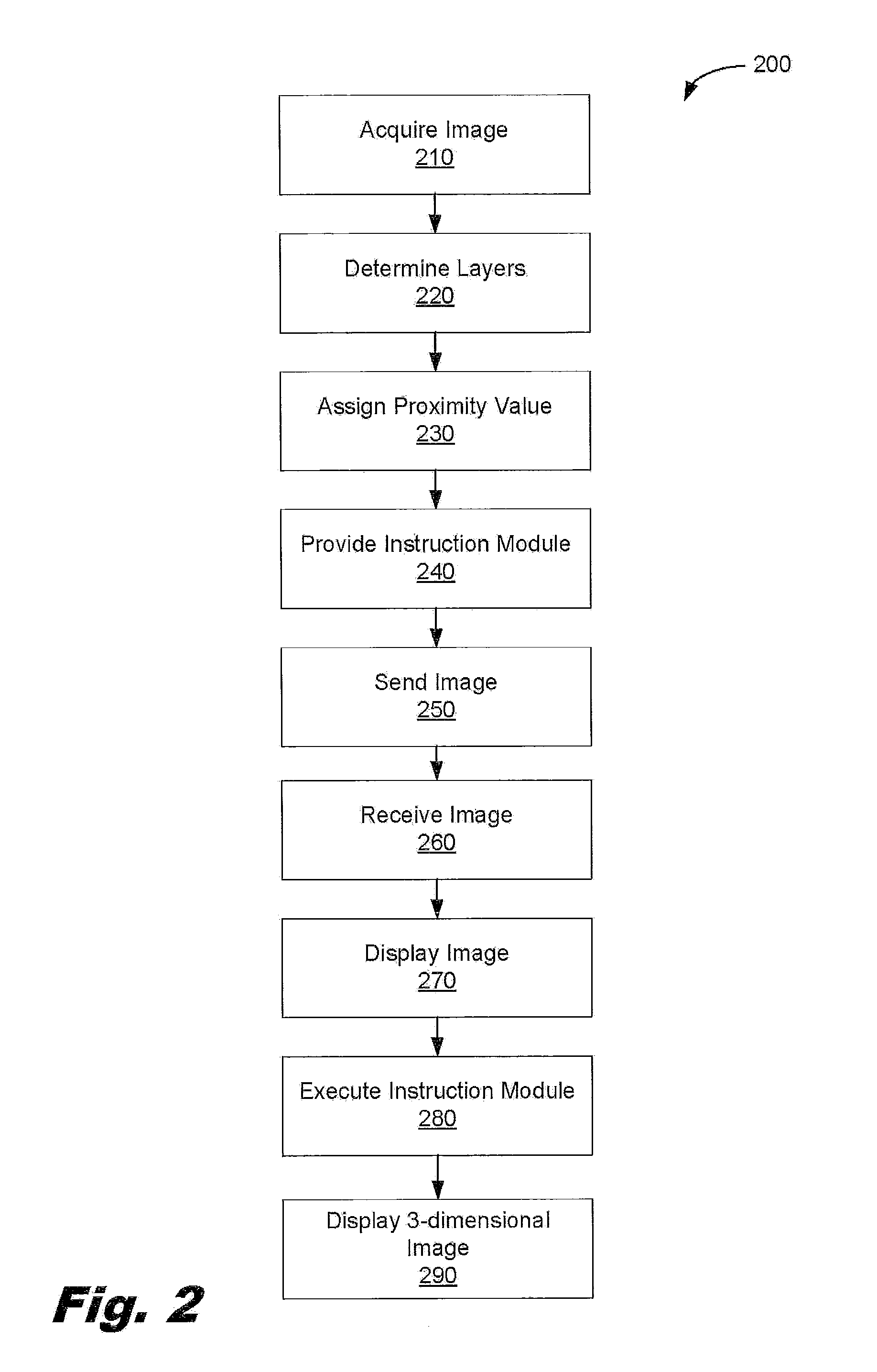
[0009]In accordance with certain illustrated embodiments of the invention, disclosed is a method and system for generating a 3-dimensional image on a 2-dimensional display of a device. The method includes the steps of receiving an image in image processor means and using the image processor means to determine two or more pixels layers in the image. A proximity value is then assigned to each pixel layer wherein the proximity value is indicative of a depth perception of the pixel layer relative to a user of a device having a display screen. An instr

Problems solved by technology

With this combination, a full true color image is not obtained, and this color combination may cause eye fatigue, and color suppression.
Thus, the prior art generally required complex specialized equipment for the transmission of 3-dimensional images.
This inhibited the use of 3-D technology because much capital investment has been devoted to equipment for handling regular 2-dimensional images.

Method used


Image

  • System and method for the creation of 3-dimensional images
  • System and method for the creation of 3-dimensional images
  • System and method for the creation of 3-dimensional images

Examples


Embodiment Construction

[0016]The present invention is now described more fully with reference to the accompanying drawings, in which an illustrated embodiment of the invention is shown. The invention is not limited in any way to the illustrated embodiment as the illustrated embodiment described below is merely exemplary of the invention, which can be embodied in various forms, as appreciated by one skilled in the art. Therefore, it is to be understood that any structural and functional details disclosed herein are not to be interpreted as limiting the invention, but rather are provided as a representative embodiment for teaching one skilled in the art one or more ways to implement the invention. Furthermore, the terms and phrases used herein are not intended to be limiting, but rather are to provide an understandable description of the invention.

[0017]It is to be appreciated that the embodiments of this invention as discussed below may be incorporated as a software algorithm, program or code residing in f...


PUM


Abstract

The invention relates to a method and system for generating a 3-dimensional image on a 2-dimensional display of a device. The method includes the steps of receiving an image in image processor means and using the image processor means to determine at least two pixels layers in the image. A proximity value is then assigned to each pixel layer wherein the proximity value is indicative of a depth perception of the pixel layer relative to a user of a device having a display screen. An instruction module is then coupled to the image operative to cause each pixel layer to move along an axis of orientation on the 2-dimensional display of the device and at a velocity rate dependent upon the proximity value assigned to the pixel layer.

Description

CROSS REFERENCE TO RELATED APPLICATIONS[0001]This patent application claims the benefit of priority under 35 U.S.C. Section 119(e) from U.S. Provisional Application Ser. No. 61 / 325,968, filed on Apr. 20, 2010, which is hereby incorporated by reference as if set forth in its entirety herein.FIELD OF THE INVENTION[0002]This invention relates generally to the field of image processing and more particularly to the creation and presentation of 3-dimensional (3-D) images on a 2-dimensional viewing surface.BACKGROUND OF THE INVENTION[0003]Since the invention of the stereoscope in 1847, there has been a desire for emulating the 3-D images instead of being content with two dimensional images which lack realism due to the absence of depth cues. Various techniques have been devised and developed for producing 3-D images, each varying in degree of success and quality of image. These techniques generally belong to two major classes, namely the autostereoscopic imaging class which produces 3-D im...

Claims


Application Information

Patent Timeline
IPC IPC(8): G06T15/00
CPCG06T2215/16G06T15/20
Inventor SEGAL, EDO
Owner BMUSE GRP
Learn More