
Athleticism rating and performance measuring system

a performance measurement and athlete technology, applied in gymnastics, instruments, nuclear elements, etc., can solve the problems of best athletes not being determined and rewarded, and efforts to meaningfully evaluate the timing and other information gathered from these exercises and drills, etc., to achieve quick, easy, accurate collection

Active Publication Date: 2011-10-13
NIKE INC
View PDF8 Cites 1 Cited by
  • Summary
  • Abstract
  • Description
  • Claims
  • Application Information

AI Technical Summary

Benefits of technology

This solution enables objective and accurate evaluation of athletic performance, minimizing human error and providing a universal standard for comparing athletes, making it accessible for routine training and evaluation across different locations.

Problems solved by technology

Scouts tour the country viewing potential athletes for particular teams, and many top athletes are recruited site unseen, simply by word of mouth: These methods for evaluating and recruiting athletes are usually hit or miss.
Accordingly, they are subject to human perception and the error inherent in it.
These variances and errors in human perception can lead to the best athlete not being determined and rewarded.
Moreover, efforts to meaningfully compile and evaluate the timing and other information gathered from these exercises and drills have been limited.
For example, while the fastest athlete from a group of athletes through a given drill may be determinable, these known systems do not allow that athlete to be meaningfully compared to athletes from all over the world that may not have participated in the exact same drill on the exact same day.
These devices are usually expensive and complex, making them difficult to set-up, calibrate, and operate effectively.
These facilities are often not regularly accessible to athletes for routine training purposes.
Moreover, the data compiled by these devices is often not meaningfully compiled and accessible for athlete evaluation and comparison purposes.

Method used


Image

  • Athleticism rating and performance measuring system
  • Athleticism rating and performance measuring system
  • Athleticism rating and performance measuring system

Examples


case 1

[0118]Coach Display Usage

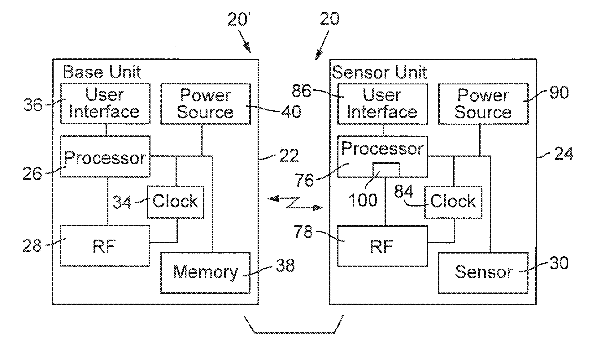
[0119]When a coach is handling the base unit 22, this unit must be in the RF range of all the sensor devices simultaneously. This results from the fact that the base unit will not, in general, be moving between the different sensor devices in the system as it is operating. In order to handle this situation, the RF range 262 for the base unit must reach all the sensors for the system. Note that this does not mean that the sensor units must be able to communicate with each other. This situation is shown in FIG. 7A (B=Base Unit, S1=Sensor Unit 1, S2=Sensor Unit 2). In this layout, the base unit is always able to communicate with each of the sensor nodes.

[0120]The setup of the training drills will vary widely and likely span a fairly sizeable distance in some situations. To handle this variability, the system needs to support an RF range that is sufficiently large to reach all the sensors. As this range grows, the wireless components must increase their transmit...

case 2

[0121]Athlete Display Usage

[0122]When an athlete is using the system alone, he or she will generally want the base unit attached to his or her body. Ideally, this could be in a suitable form factor such as a wrist mounted watch or the like. In this configuration, the system can function the same way it does in the first case. However, the added complexity of the RF link and the increase in power usage may be undesirable to support in this situation. Since that athlete will be physically close to the sensor units when the sensor measurements are made, the power of the RF transmissions could be significantly reduced. This would both reduce the system power requirements and reduce the transmitted RF power levels to the state where a simpler RF implementation is possible. This situation is shown in FIG. 7B using the same element names and numbers as in the previous discussion of FIG. 7A.

[0123]The key to this system is that the base unit 24 is located physically close to a sensor unit 24...

case 3

[0124]Coach and Athlete Display Usage

[0125]In order for both the athlete and the coach to track the timing information, there are several possible implementations. In one implementation, the same architecture as for case 1 to communicate between the coach unit and the sensor units could be used. The coach unit could then resend, possibly with a different protocol or with a different RF frequency band, the performance data to the athlete unit for display. Likely the RF performance of the wearable device would only support a simple protocol, operate with a short range, and need to be near the base unit in order to operate successfully. This situation is shown in FIG. 6A using the same element names and numbers as in the previous discussion of FIG. 7A.

[0126]In this case, the base unit 22 is actually operating two RF communication links. The first link is used to communicate with the sensor units much the same way as described in case 1. This link would be implemented for longer-range o...


PUM


Abstract

A universal athleticism rating system and related athletic performance measuring systems for accurately detecting and recording athletic performance are disclosed. The athleticism rating system evaluates individual athletes against a common, standardized, set of athletic performance tests. Each athlete performs the athletic tests and his or her scores in the individual tests are entered into a standardized calculation to produce a single athletic performance score. The related performance measuring system is preferably a timing system that ensures quick, easy, and accurate collection of athletic event timing related data without the need for the athlete to wear any special detection devices or the like. In a preferred embodiment, the performance measuring system integrates with the rating system to provide seamless athletic data collection and rating of athletes.

Description

CROSS-REFERENCE TO RELATED APPLICATIONS[0001]This application is a continuation of and claims priority to U.S. patent application Ser. No. 11 / 269,161 filed on Nov. 7, 2005, which application claims priority to U.S. provisional patent application Ser. No. 60 / 625,482 filed on Nov. 5, 2004, and U.S. provisional patent application Ser. No. 60 / 688,518 filed on Jun. 7, 2005. This application is also related to copending U.S. patent application Ser. No. 12 / 718,854 filed on Mar. 5, 2010, which is a divisional of U.S. patent application Ser. No. 11 / 269,161. The disclosures of all of these applications are hereby incorporated by reference in their entirety for any and all purposes.FIELD OF THE INVENTION[0002]The present invention relates to athleticism rating and related performance measuring systems for use primarily with athletic activities such as training and evaluating athletes and the like.BACKGROUND OF THE INVENTION[0003]Athletics are extremely important in our society. In addition to ...

Claims


Application Information

Patent Timeline
Patent Type & Authority Applications(United States)
IPC IPC(8): G06F15/00
CPCA63B24/0006A63B71/0619A63B71/06A63B71/0616A63B2024/0009A63B2024/0012A63B2024/0065A63B2024/0068A63B2071/026A63B2071/0661A63B2071/0663A63B2220/12A63B2220/13A63B2220/805A63B2225/093A63B2225/15A63B2225/20A63B2225/50A63B2243/0004A63B2243/0025A63B2243/0037A63B2243/007G06F1/1626A63B2024/0071G07C1/22A63B24/0062A63B2102/18A63B71/03A63B2243/0066
Inventor CHAPA, JR., RODOLFOARJOMAND, HAMID G.BRAUN, ADAM C.BARK, ANDREW
Owner NIKE INC
Learn More