Combined sealing device for a rotary shaft

Inactive Publication Date: 2011-10-13
BEIJING JIAOTONG UNIV
View PDF16 Cites 12 Cited by
  • Summary
  • Abstract
  • Description
  • Claims
  • Application Information

AI Technical Summary

Benefits of technology

[0003]The object of the present invention is to provide a combined sealing device for a rotating machinery so as to seal liquid under harsh conditions such as low temperature, no pollution and no leakage.
[0008]With the beneficial effects of the invention, the invention applies the combined sealing style of a spiral seal and a magnetic fluid seal which are both non-contact seals and non-friction parts, so it has a long service life, a high seal reliability, a zero leakage, and no pollution, and a low installation precision is required by the spiral seal, When the rotary shaft is in motion or at rest, the magnetic fluid plays a role of seal and makes the spiral seal without any additional stop seal. The combined sealing device is a compact construction device which is easy to install and easy to operate.

Problems solved by technology

At present, the research of gas seal in a rotating machinery is relatively too much and mature, but the research of a liquid seal, especially under harsh conditions such as low temperature, no pollution and no leakage, is relatively few.
Although the packing seal has advantages such as simple structure and easy operation, the larger friction and wear between the packing and the rotating parts, more power consumption, and unreliable seal have been noted unfortunately.
Under present circumstances, the problem of liquid leakage cannot be solved completely by applying some sealing method alone.
Therefore, it is a big challenge to improve the liquid sealing property in the rotating machinery.

Method used


Image

  • Combined sealing device for a rotary shaft
  • Combined sealing device for a rotary shaft

Examples


Embodiment Construction

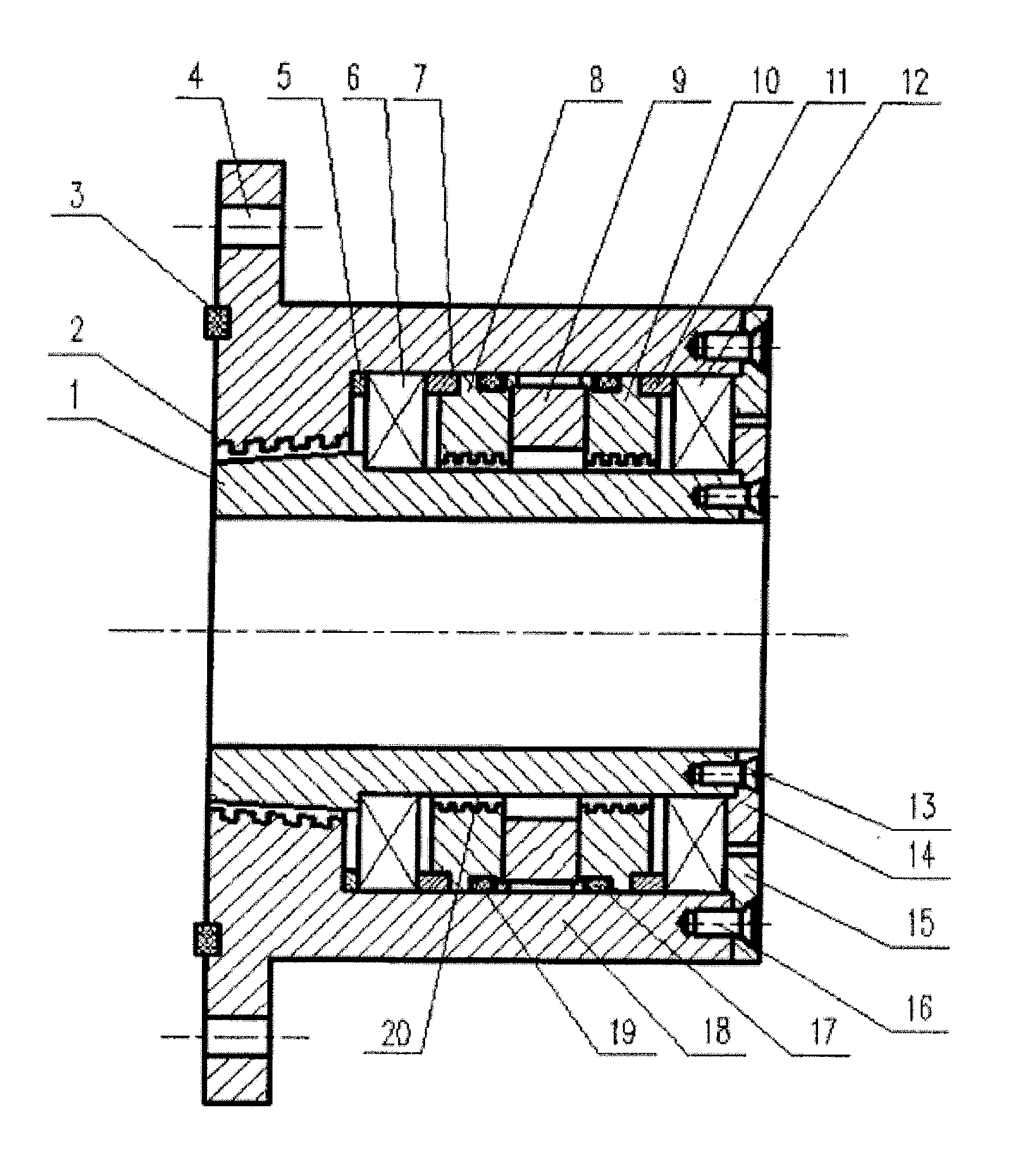
[0011]A further explanation of this invention is made with the accompanying drawing, as shown in FIG. 1.

[0012]It is provided a combined sealing device for a rotary shaft, in which the seal consists of a conical spiral groove seal and a magnetic fluid seal.

[0013]This combined sealing device includes the shaft housing 1, the rubber sealing ring 3, the circular ring 5, the left bearing 6, the left septum magnetic ring 7, the magnetic fluid sealing assembly, the right septum magnetic ring 11, the right bearing 12, the screw nails 13, the first end cover 14, the second end cover 15, the screw nails 16, the right rubber sealing ring 17, a housing 18, and the left rubber sealing ring 19.

[0014]The magnetic fluid sealing assembly consists of the left pole piece 8, the permanent magnet 9, and the right pole piece 10, in which the left pole piece 8, the permanent magnet 9, and the right pole piece 10 are bonded together in series. The rubber sealing ring 17 is installed inside an annular groov...


PUM


Abstract

A combined sealing device for a rotary shaft, in which the combined sealing device comprises the ring (5), the left bearing (6), the left septum magnetic ring (7), a magnetic fluid sealing assembly, the right septum magnetic ring (11), and the right bearing (12) which are arranged inside a housing (18) in series, after the magnetic fluid is injected into the pole teeth of pole pieces in the magnetic fluid sealing assembly, the shaft housing is loaded into the inner hole of the above-mentioned parts, then the second end cover (15) is fixed on a housing by screw nails (16) to press the outer ring of the right bearing tightly, after that, the first end cover (14) is fixed on the shaft housing (1) by screw nails (13) to press the inner ring of right bearing tightly, so that a magnetic fluid seal is device is achieved, the left end external surface of the shaft housing is the conical surface, and the left end inner hole of the housing is the taper hole which has the same taper as the left end of shaft housing and in which spiral groove is processed, the left end external conical surface of the shaft housing coordinates with the left end spiral groove of the housing provided in the taper hole, so that a conical spiral seal is achieved. This device has the advantages such as a long service life, a reliable seal, and no pollution.

Description

FIELD OF THE PRESENT INVENTION[0001]This invention relates to a combined sealing device for a rotary shaft, which belongs to the field of mechanical seals.BACKGROUND OF THE PRESENT INVENTION[0002]At present, the research of gas seal in a rotating machinery is relatively too much and mature, but the research of a liquid seal, especially under harsh conditions such as low temperature, no pollution and no leakage, is relatively few. In recent years, the liquid seal in the rotating machinery mainly applies a packing seal. Although the packing seal has advantages such as simple structure and easy operation, the larger friction and wear between the packing and the rotating parts, more power consumption, and unreliable seal have been noted unfortunately. Under present circumstances, the problem of liquid leakage cannot be solved completely by applying some sealing method alone. Therefore, it is a big challenge to improve the liquid sealing property in the rotating machinery.SUMMARY OF THE ...

Claims


Application Information

Patent Timeline
IPC IPC(8): F16J15/43
CPCF16J15/43
Inventor LI, DECAIYANG, XIAOLONG
Owner BEIJING JIAOTONG UNIV
Why Eureka
Try Eureka