
Screen Adjustment Device for a Motor Vehicle

a technology for motor vehicles and adjustment devices, which is applied in the direction of suspension devices, machine supports, applications, etc., can solve the problems of affecting the overall space available in the motor vehicle for accommodating the screen, and the difficulty of fitting the device in the motor vehicle. achieve the effect of improving the degree of prefabrication of the screen adjustment devi

Active Publication Date: 2011-10-13
BROSE FAHRZEUGTEILE GMBH & CO KG
View PDF6 Cites 12 Cited by
  • Summary
  • Abstract
  • Description
  • Claims
  • Application Information

AI Technical Summary

Benefits of technology

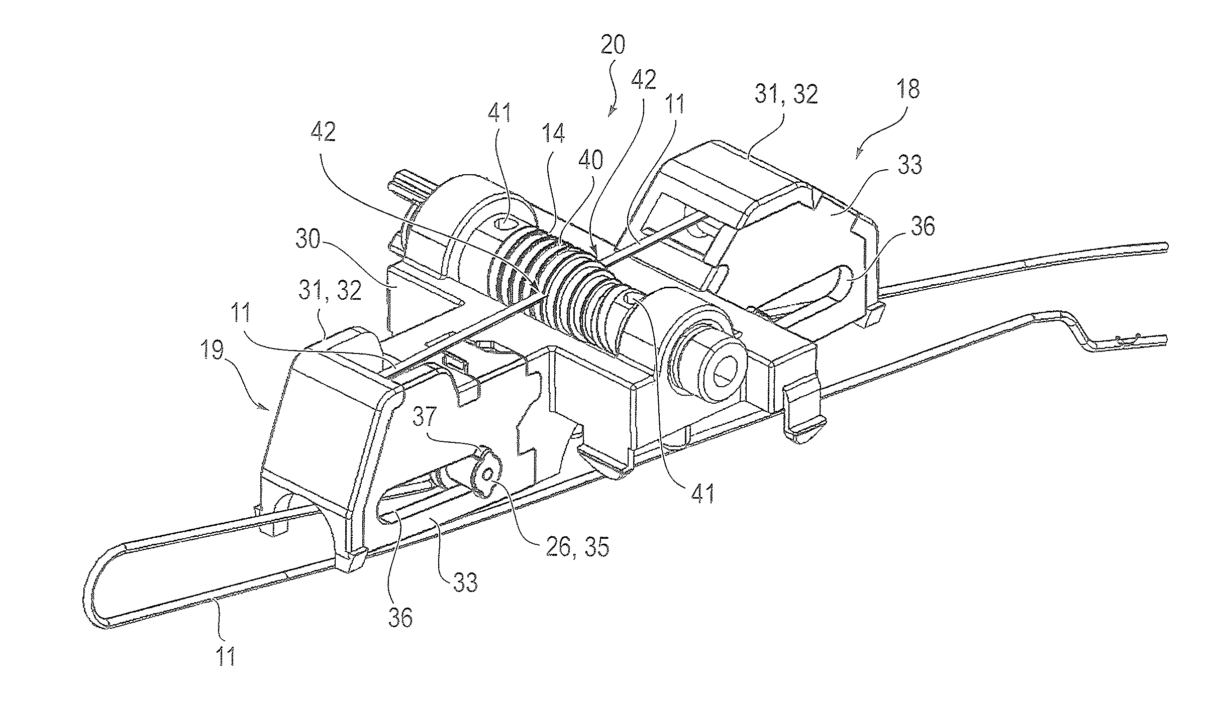
[0013]The invention in certain embodiments is based on the consideration that, instead of a toothed rack drive, for a screen adjustment device of the aforementioned type it is advantageously possible to use a control cable drive, especially since the latter lends itself to particularly flexible and straightforward adaptation to restricted overall spaces and complex movement paths. One disadvantage to a conventional control cable drive, however, is the known fact that this usually comprises a large number of isolated small parts, such as return sheaves, tensioning rollers, etc., which in turn would complicate the process of assembling the control cable drive in the motor vehicle. This forms the point of departure for certain embodiments of the invention. Since according to certain embodiments of the invention at least the core of the control cable drive, that is to say the bearing block for or with the winding reel, and the cable tensioning unit are or can be pre-assembled, the production process can be substantially simplified. The simplification lies, in particular, in the fact that assembly of the control cable drive, comprising small parts which are therefore difficult to assemble, in this respect does not have to be undertaken under the restricted spatial conditions in the motor vehicle, but can be done separately from this in an unconfined area. In particular, the scope for at least partial pre-assembly of the control cable drive furthermore allows this to be prefabricated, particularly by a supplier, at a separate location to that of final assembly of the motor vehicle.
[0016]At least the fixed return element is suitably integrally formed with the bearing block. In a simple configuration the return elements of the cable tensioning unit are preferably formed by spindles, which are held rotationally fixed on the housing of the tensioning unit. Alternatively, however, the return elements may also be formed by rollers. In the latter case the roller corresponding to the fixed return element is suitably supported on a spindle integrally formed with the bearing block.

Problems solved by technology

Since the overall space available in a motor vehicle for accommodating the screen in the parked position is generally severely restricted, motor vehicle screens often have to be moved over a complex adjustment travel between the open position and the parked position.
The complexity of such screen adjustment devices and the limited scope for installing such a device in a motor vehicle often make it difficult and time-consuming to fit the device in a motor vehicle.
One disadvantage to a conventional control cable drive, however, is the known fact that this usually comprises a large number of isolated small parts, such as return sheaves, tensioning rollers, etc., which in turn would complicate the process of assembling the control cable drive in the motor vehicle.
This is important particularly in view of the fact that in the area of the open position of the screen the control cable drive generally has to apply an especially high tensile force in order to adjust the screen, owing to the unfavorable leverage ratios.

Method used


Image

  • Screen Adjustment Device for a Motor Vehicle
  • Screen Adjustment Device for a Motor Vehicle
  • Screen Adjustment Device for a Motor Vehicle

Examples


Embodiment Construction

[0033]The (screen adjustment) device 1 shown only in rough schematic form in FIGS. 1 to 5 is substantially formed by a screen carrier 2, a guide path 3 and a control cable drive 4.

[0034]Fixed to a front side 5 of the screen carrier 2 is a screen 6. At the rear a (plate or lever-type) guide contour 7, which engages positively with a catch 8 in the guide path 3, is fitted to the screen carrier 2. Here the screen carrier 3 can on the one hand be displaced with this catch 8 along the guide path 3. On the other hand the screen carrier 2 can be swiveled about the catch 8.

[0035]The guide path 3 extends substantially horizontally inside a dashboard 9 (indicated only roughly) of a motor vehicle above a mount 10 provided therein for the screen carrier 2 and the screen 6 affixed to the latter.

[0036]The control cable drive 4 comprises a control cable 11, which is guided over two main return points 12, 13 on to a winding reel 14.

[0037]The main return elements 12,13 are rotationally fixed spindle...


PUM


Abstract

A screen adjustment device (1) for a motor vehicle has a screen (6) or screen carrier (2) for mounting a screen, and a control cable drive (4) for adjusting the screen or screen carrier between an open (screen-accessible) position (22) and a parked (screen-hidden) position (24). The control cable drive has a control cable (11), which is coupled to the screen or screen carrier by a driver (15) and which at the two ends is guided over two return elements (12, 13) and at least one cable tensioning unit (18, 19) onto a winding reel (14) coupled to a drive motor (21). The control cable drive has a bearing block (30) for supporting the winding reel, the block together with the cable tensioning unit forming a self-contained pre-assembled unit (20) or being capable of pre-assembly to form such a unit.

Description

BACKGROUND[0001]1. Field of the Invention[0002]The invention relates to a screen adjustment device for a motor vehicle.[0003]2. Description of the Related Art[0004]In modern motor vehicles a screen, which serves as output interface of an on-board computer for displaying various ambient and operating variables, such as the outdoor temperature, the fuel consumption etc., is often provided in the area of the dashboard. In addition or alternatively, such a screen often also serves as an output unit of a navigation system, car radio, etc. If a touch-sensitive screen is used or separate operating elements are assigned to a display which in itself is non-touch-sensitive, such a screen may also be provided as an input interface for the on-board computer, the navigation system or the car radio.[0005]Screens are furthermore also used in the rear area of the vehicle passenger compartment of a motor vehicle. Here these screens primarily form part of a multimedia entertainment system (rear seat ...

Claims


Application Information

Patent Timeline
Patent Type & Authority Applications(United States)
IPC IPC(8): B60J3/02
CPCB60K35/00B60K37/06B60R11/0235B60K2350/1028B60K2350/1024B60K35/10B60K2360/143B60K2360/1438
Inventor DIETZEL, RENEESTEGNER, DANIELA
Owner BROSE FAHRZEUGTEILE GMBH & CO KG
Learn More