User interface device and method

a user interface and user technology, applied in the field of user interface devices and methods, can solve the problems of cumbersome device holding, difficult to control the size of the device, complicated interface devices, etc., and achieve the effect of convenient operation and convenient operation

Inactive Publication Date: 2011-10-06
KONINKLIJKE PHILIPS ELECTRONICS NV
View PDF15 Cites 9 Cited by
  • Summary
  • Abstract
  • Description
  • Claims
  • Application Information

AI Technical Summary

Benefits of technology

[0004]The present invention seeks to provide a user interface which is of a size and weight small enough not to hinder the user in the daily operation and to provide a user interface that is convenient and easy to operate.
[0008]This allows a user to interact with the user interface device by bending a flexible part, while simultaneously maintaining a secure grip on the user interface device by holding the non-flexible part. Furthermore, by providing a non-flexible part coupled to the flexible part, unnecessary expense can be avoided in that there is no requirement for all components of the user interface device to be flexible. As a result the device can be small enough for the convenience of the user whilst not hindering the transfer of commands, for example, it can be manipulated by one hand. Further, the device is formed of a small number of parts whilst offering a large variability of the number of functions (or commands) that can be implemented. Further, the device is easy to use as commands are generated using intuitive gestures of the user.
[0010]The sensors may be coupled to the non-flexible part and the flexible part. The sensors may be configured to sense bending at an interface between the flexible parts and the non-flexible part. Thus increasing the sensitivity of the device by degrees of movement to generate a variety of commands from a simple device.
[0012]Detecting the bending of the flexible part may comprise detecting a change in voltage produced by deformation of a piezoelectric material, or detecting a change in current passed by a quantum tunnelling composite upon deformation. In this way a simple and effective technique is utilised to detect bending and generate a command as required.

Problems solved by technology

Further, developments of such user interface devices have evolved such that the interface devices are more complex including commonly used functions (such as play, fast forward, on / off etc.) where buttons or combinations of buttons are used to capture commands from the user to be sent to the electronic system connected to the interface device.
However, the buttons or combinations of buttons are problematical in very small devices.
However, the device is cumbersome to hold and the flexing of the display makes fine changes difficult to control.

Method used


Image

  • User interface device and method
  • User interface device and method

Examples


Embodiment Construction

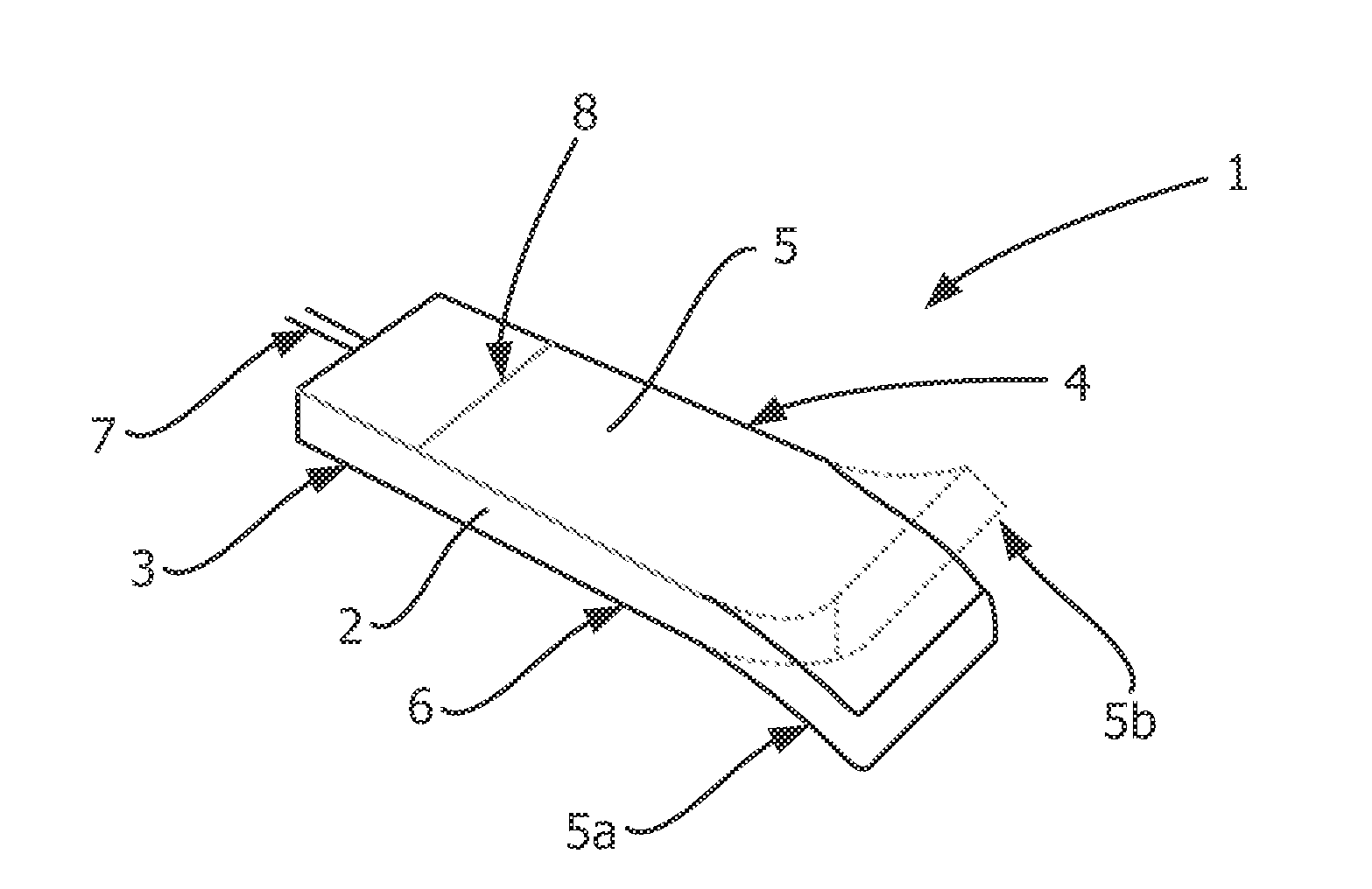
[0017]Referring to FIG. 1, a user interface device 1 comprises a substantially rectangular member 2 having substantially planar upper and lower surfaces 4 and 6. The rectangular member 2 comprises a base portion 3 constructed to be non-flexible and a flexible portion 5 formed from a polymer such as silicone or rubber. The user interface device 1 further comprises a wire 7 extending from the base portion 3 for connecting the user interface device 1 to a music playback device or the like (not shown).

[0018]The flexible portion 5 may be deflected from a non-bent position 5a into a bent position 5b upon the application of a force from a user in a direction perpendicular to the plane of the upper and lower surfaces 4, 6 of the rectangular member 2. At least one sensor (not shown) inside the user interface device 1 detects the deflection and produces a command that is transmitted down the wire 7 to the music playback device. The sensor may comprise a piezoelectric sensor or a quantum tunne...


PUM


Abstract

A user interface device (1) comprises a non-flexible part (3); at least one flexible part (5) coupled to the non-flexible part (3); and at least one sensor, for detecting bending of a respective flexible part (5) with respect to the non-flexible part (3), and for producing a command in response to sensing bending of the respective flexible part (5).

Description

FIELD OF THE INVENTION[0001]The present invention relates to a user interface device and a method of controlling a device via a user interface device. In particular, but not exclusively, the present invention relates to a bendable user interface device.BACKGROUND OF THE INVENTION[0002]Many electronic systems have a user interface which comprises a visual indicator and a device which navigates the visual indicator enabling the user to interact with the system. These user interface devices are commonly remote from the system and connected to the system via a wired connection or wireless connection. A simple example of such a user interface device is volume control on the connection leads of a pair of headphones of a portable audio player. The volume control is more conveniently placed for the user to adjust the volume without a need to retrieve the audio player itself which may be placed in a pocket or bag etc. Further, developments of such user interface devices have evolved such tha...

Claims


Application Information

Patent Timeline
IPC IPC(8): G05B19/02G06F3/033G06F3/0489
CPCG06F3/033G06F3/0202G06F3/0487G06F3/017G06F3/0362G06F3/01G06F3/0354G06F3/045G06F1/1652G06F1/1656G06F1/1626
Inventor OPRAN, CONSTANTIN ALEXANDRUTSANG, PETER TJIN SJOE KONGPILL, STUART RONALDBINK, CORNELIS PETRUS JOSEPH
Owner KONINKLIJKE PHILIPS ELECTRONICS NV
Why Eureka
Try Eureka