
Pierce gun and method of controlling thereof

a technology of electron gun and piercing device, which is applied in the direction of instruments, static indicating devices, x-ray tubes, etc., can solve the problems of voltage control, control and limitation of the power needed to keep the emitter operating properly, and achieve the effect of reducing the operating temperature of the electron emitter and the filamen

Active Publication Date: 2011-10-06
GENERAL ELECTRIC CO
View PDF8 Cites 71 Cited by
  • Summary
  • Abstract
  • Description
  • Claims
  • Application Information

AI Technical Summary

Benefits of technology

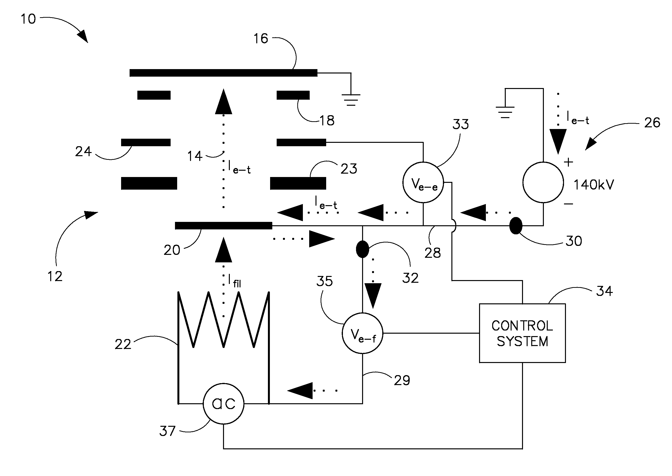
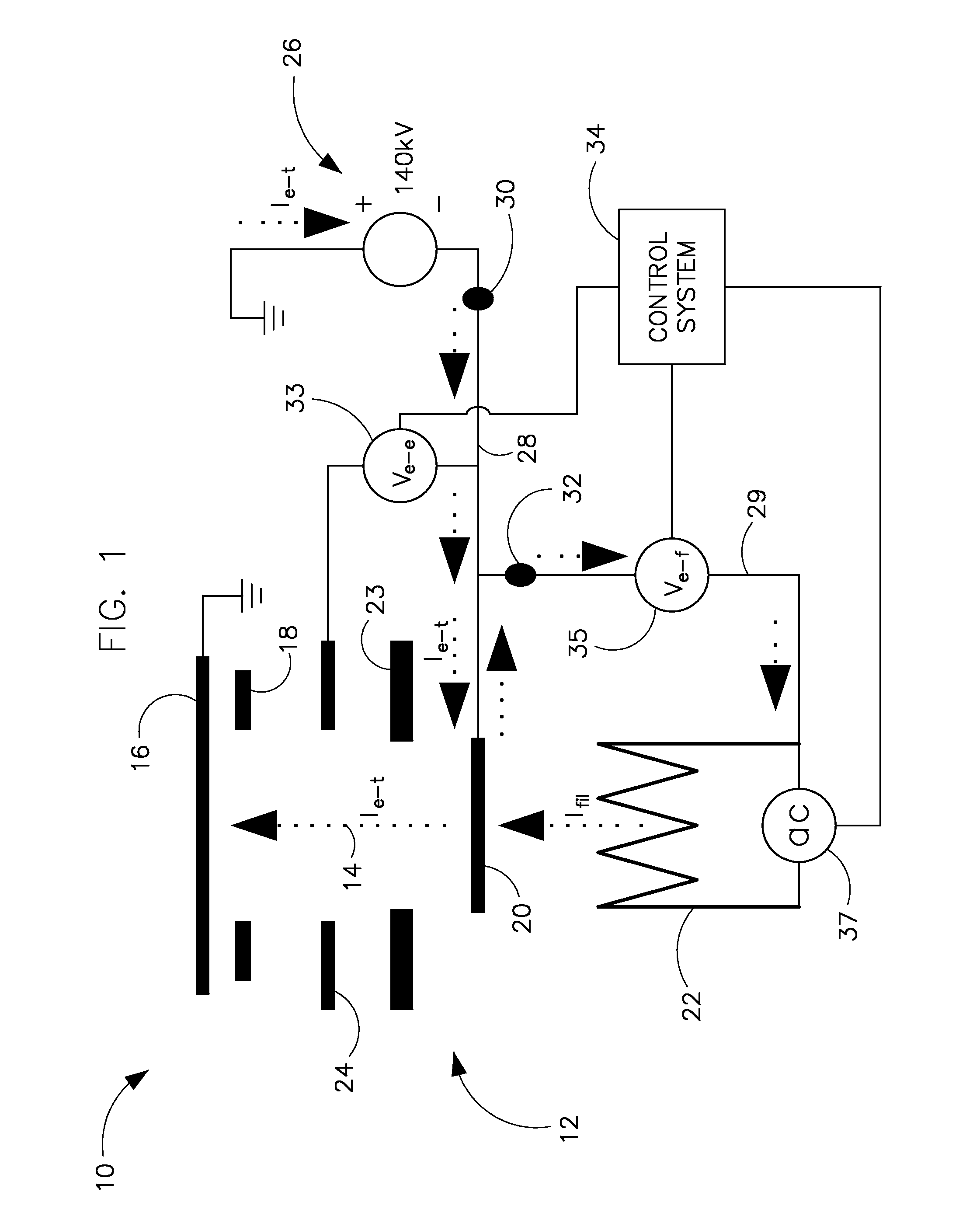
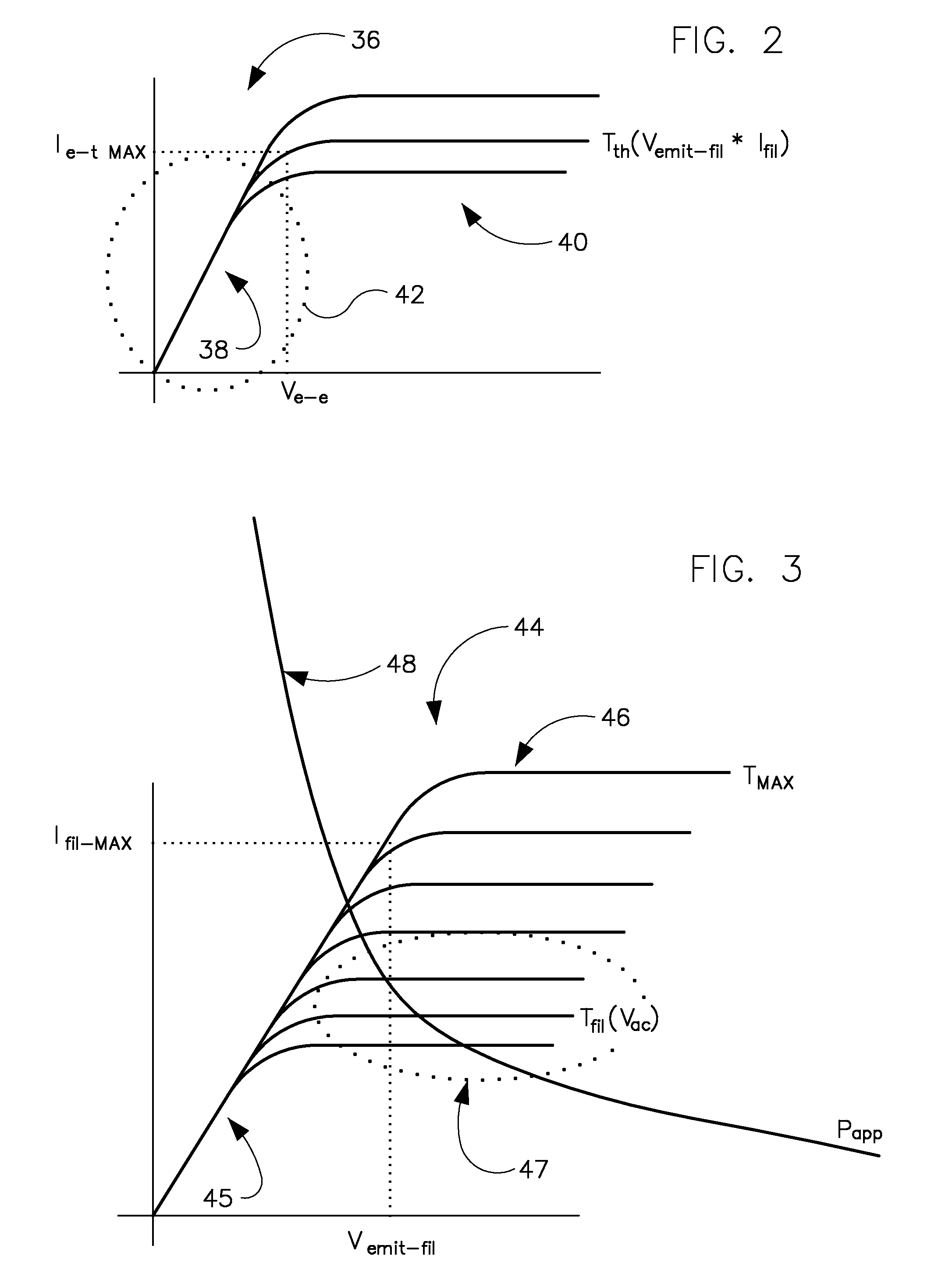
[0007]According to one aspect of the invention, an apparatus includes a filament configured to generate heat when a voltage is applied thereto, an electron emitter heated by the filament to generate an electron beam, and a power supply configured to supply power to each of the filament and the electron emitter, the power supply including a plurality of voltage supplies. The apparatus also includes a control system to control a supply of power to each of the filament and the electron emitter, with the control system being configured to receive an input indicative of a desired electron emitter operating temperature, cause a desired voltage to be applied between the electron emitter and the filament, and cause a desired voltage to be applied to the filament based on the desired emitter element operating temperature, so as to minimize an operating temperature of the electron emitter and the filament.

Problems solved by technology

One drawback to existing Pierce-type electron guns is the control of voltage, and the control and limitation of the power needed to keep the emitter and filament at the proper operating temperatures.

Method used


Image

  • Pierce gun and method of controlling thereof
  • Pierce gun and method of controlling thereof
  • Pierce gun and method of controlling thereof

Examples


Embodiment Construction

[0022]Referring to FIG. 1, a block schematic diagram of an apparatus 10 is depicted according to one embodiment of the invention. Apparatus 10 is configured to control the temperature of both an electron emitter 20 and a filament 22 included therein such that the electron emitter and filament 22 are kept to their lowest possible operating temperature. According to an exemplary embodiment of the invention, apparatus 10 is a Pierce-type of electron gun that includes a cathode structure, generally designated by the number 12, configured to generate a beam of electrons 14 that is directed from cathode 12 to the beveled periphery (not shown) of a target anode 16. The electron beam 14 is focused in a spot from which a beam of X-rays emanates as anode 16 rotates. Also included in electron gun 10 is an accelerating anode assembly 18 (i.e., formed as a beam collector when implemented in an x-ray tube) interposed between cathode structure 12 and target anode 16. The electron beam 14 from cath...


PUM


Abstract

A system and method for controlling the temperature of both an electron emitter and a filament to their lowest possible operating temperature is disclosed. The apparatus includes a filament, an electron emitter heated by the filament to generate an electron beam, and a power supply configured to supply power to each of the filament and the electron emitter. The apparatus also includes a control system to control a supply of power to each of the filament and the electron emitter, with the control system being configured to receive an input indicative of a desired electron emitter operating temperature, cause a desired voltage to be applied between the electron emitter and the filament, and cause a desired voltage to be applied to the filament based on the desired emitter element operating temperature, so as to minimize an operating temperature of the electron emitter and the filament.

Description

BACKGROUND OF THE INVENTION[0001]The present invention relates generally to a Pierce-type electron gun, and, more particularly, to a system and method for controlling operation of a Pierce-type electron gun to control current density in the electron beam and control the operating temperature of the electron emitter and the filament, so as to keep the temperature of both the electron emitter and the filament to their lowest possible operating temperature.[0002]X-ray tubes typically include a cathode structure that provides an electron beam that is accelerated using a high voltage applied across a cathode-to-anode vacuum gap to produce x-rays upon impact with a rotating anode. The area where the electron beam impacts the anode is often referred to as the focal spot. Typically, the cathode includes one or more cylindrical or flat filaments positioned within a cup for providing electron beams to create a high-power large focal spot or a high-resolution small focal spot, as examples. Ima...

Claims


Application Information

Patent Timeline
Patent Type & Authority Applications(United States)
IPC IPC(8): H01J29/48
CPCH05G1/32H01J35/06H01J35/045
Inventor CAIAFA, ANTONIOZHANG, XIROBINSON, VANCELEMAITRE, SERGIO
Owner GENERAL ELECTRIC CO
Learn More