Electronic sphygmomanometer

a sphygmomanometer and electronic technology, applied in the field of wrist-type electronic sphygmomanometers, can solve the problems of user discomfort and inability to measure hour by hour, and achieve the effect of improving usability

Active Publication Date: 2011-09-29
OMRON HEALTHCARE CO LTD
View PDF6 Cites 22 Cited by
  • Summary
  • Abstract
  • Description
  • Claims
  • Application Information

AI Technical Summary

Benefits of technology

[0007]Therefore, one or more embodiments of the present invention provides an electronic sphygmomanometer that can improve usability while including the angle sensor to guide the position of the measurement site into the proper range.
[0016]Further, according to one or more embodiments of the present invention, the measurement can be automatically started even if the position of the measurement site is maintained out of the proper range. Therefore, the usability can be improved.
[0017]According to one or more embodiments of the present invention, when the measurement control unit outputs the measurement result, whether the position of the measurement site falls within the proper range is further notified while the position of the measurement site is correlated with the measurement result. Accordingly, the person to be measured can easily determine whether the currently-output measurement result is obtained in the proper measurement posture.

Problems solved by technology

Accordingly, for a user (person to be measured) who can hardly set the position of the measurement site into the proper range due to a physical feature (for example, a user who has difficulty in raising a wrist), the measurement cannot be performed hour by hour.
Therefore, the user may feel uncomfortable because of the measurement not being started for a long time even though the user wants to start the measurement.

Method used


Image

  • Electronic sphygmomanometer
  • Electronic sphygmomanometer
  • Electronic sphygmomanometer

Examples


Embodiment Construction

[0027]Embodiments of the present invention will be described in detail with reference to the drawings. The same reference numerals are denoted to the same or corresponding portions in the figures, and the description thereof will not be repeated.

[0028]First, an appearance and a configuration of an electronic sphygmomanometer according to an embodiment of the present invention (hereinafter referred to as a “sphygmomanometer”) will be described.

(Regarding Appearance)

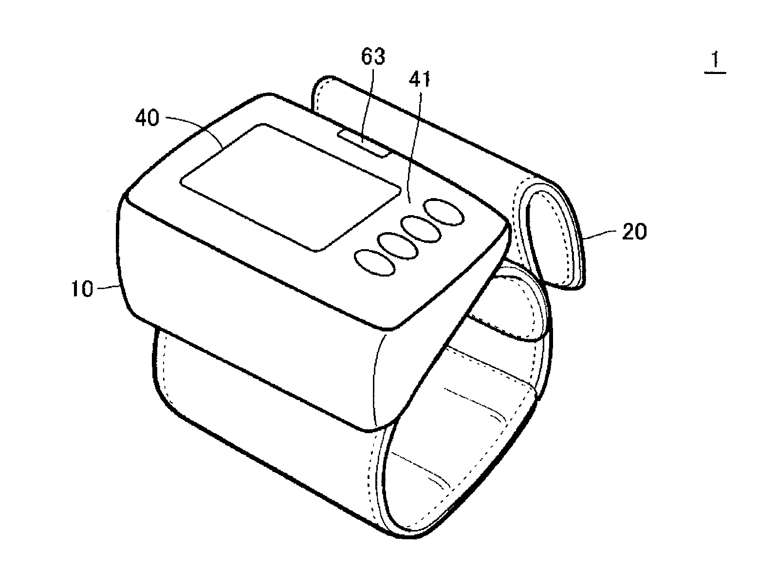
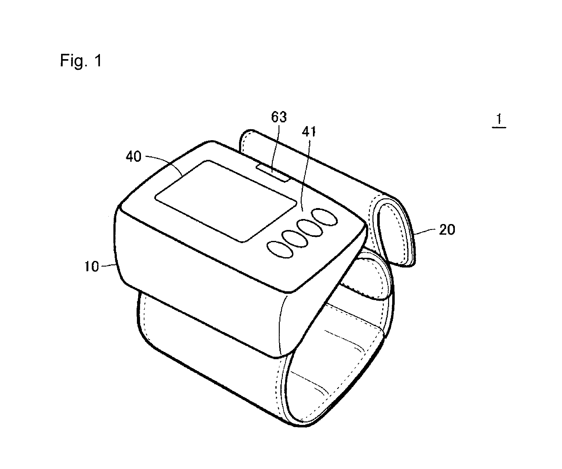
[0029]FIG. 1 is a perspective view of an appearance of a sphygmomanometer 1 according to an embodiment of the present invention.

[0030]Referring to FIG. 1, the sphygmomanometer 1 includes a main body 10 and a cuff 20 that can be worn around a wrist of a person to be measured. The main body portion 10 is attached to the cuff 20. A display unit 40 including an LCD (Liquid Crystal Display), for example, and an operation unit 41 that receives an instruction from a user (typically, person to be measured) are arranged on a surfac...


PUM


Abstract

An electronic sphygmomanometer determines whether a position of a measurement site falls within a proper range, and notifies whether the position of the measurement site falls within the proper range. When determination is made that a time in which the position of the measurement site falls within the proper range is not less than a predetermined time (for example, 2 seconds), measurement of a blood pressure is automatically started. When determination is made that a time in which the position of the measurement site is out of the proper range is not less than a predetermined time (for example, 5 seconds), the measurement of the blood pressure is started. Further, whether the position of the measurement site falls within the proper range is notified while correlated with the measurement result.

Description

TECHNICAL FIELD[0001]The present invention relates to an electronic sphygmomanometer, particularly to a wrist type electronic sphygmomanometer that can determine whether a position of a blood pressure measurement site falls within a proper range.BACKGROUND ART[0002]Generally, in a sphygmomanometer, a blood pressure value can correctly be obtained by performing measurement in a state in which a position of a blood pressure measurement site is aligned with a height of a heart. This is because, due to a weight of the blood pressure, the blood pressure value is increased when the measurement site is measured at a position lower than the heart and the blood pressure value is decreased when the measurement site is measured at a position higher than the heart.[0003]Therefore, as illustrated in International Publication WO 2002 / 039893 (Patent Document 1), there is a wrist type sphygmomanometer that includes angle detection means (angle sensor) to determine whether a measurement posture is p...

Claims


Application Information

Patent Timeline
IPC IPC(8): A61B5/0225
CPCA61B5/022A61B5/02225A61B5/025A61B5/061A61B2560/0261A61B5/6824A61B5/684A61B5/70A61B5/065
Inventor NISHIOKA, TAKANORISANO, YOSHIHIKOKAWANO, ATSUSHIETO, MIKAARIDOME, KENJISUZUKI, KOTAROYUMOTO, MASAHIKO
Owner OMRON HEALTHCARE CO LTD
Why Eureka
Try Eureka