
Imaging apparatus and image processing method

a technology of image processing and image processing, applied in the field of image processing, can solve the problems of reducing contrast and prior arts not providing any solution, and achieve the effect of increasing sharpness and speed of movement of subjects

Inactive Publication Date: 2011-09-29
FUJIFILM CORP
View PDF11 Cites 45 Cited by
  • Summary
  • Abstract
  • Description
  • Claims
  • Application Information

AI Technical Summary

Benefits of technology

[0005]The present invention is provided to solve the above problem; the object of the present invention is to provide a solution for making it possible to follow the course of movement of a common subject contained in images successively captured by an imaging apparatus, even if the subject movement is so fast that it is difficult to extract corresponding feature points of the subject from these images.
[0008]Alternatively, the movement judging device may judge that the speed of movement of the subject is high when the number of untraceable feature points is not less than a predetermined value.
[0011]The imaging condition changing device may raise the shutter speed or the frame rate of the image sensor up to a value appropriate for a moving subject when the movement judging device judges that the subject is moving fast.
[0013]Where the imaging apparatus comprises an AF control device having different operation modes with different focusing speeds, the imaging condition changing device may set the AF control device to a mode that achieves a higher focusing speed when the movement judging device judges that the subject is moving fast.
[0021]According to the present invention, even if the subject moves so fast that the corresponding points are difficult to identify, it is possible to determine that the speed of movement of the subject is high. In that case, by adjusting the imaging condition of the imaging apparatus to the rapidly moving subject, the imaging apparatus will be able to capture such image frames that contain the moving subject with greater sharpness.

Problems solved by technology

However, conventional methods of tracking the movement of a subject by identifying corresponding feature points of the subject between successive images of the subject generally has a problem that the corresponding feature points can be difficult to find if the subject or target object moves so fast that the consequent images suffer motion blur and thus have reduced contrast.
The above-mentioned prior arts do not provide any solution for this problem that can occur when the subject moves at a high speed.

Method used


Image

  • Imaging apparatus and image processing method
  • Imaging apparatus and image processing method
  • Imaging apparatus and image processing method

Examples


Embodiment Construction

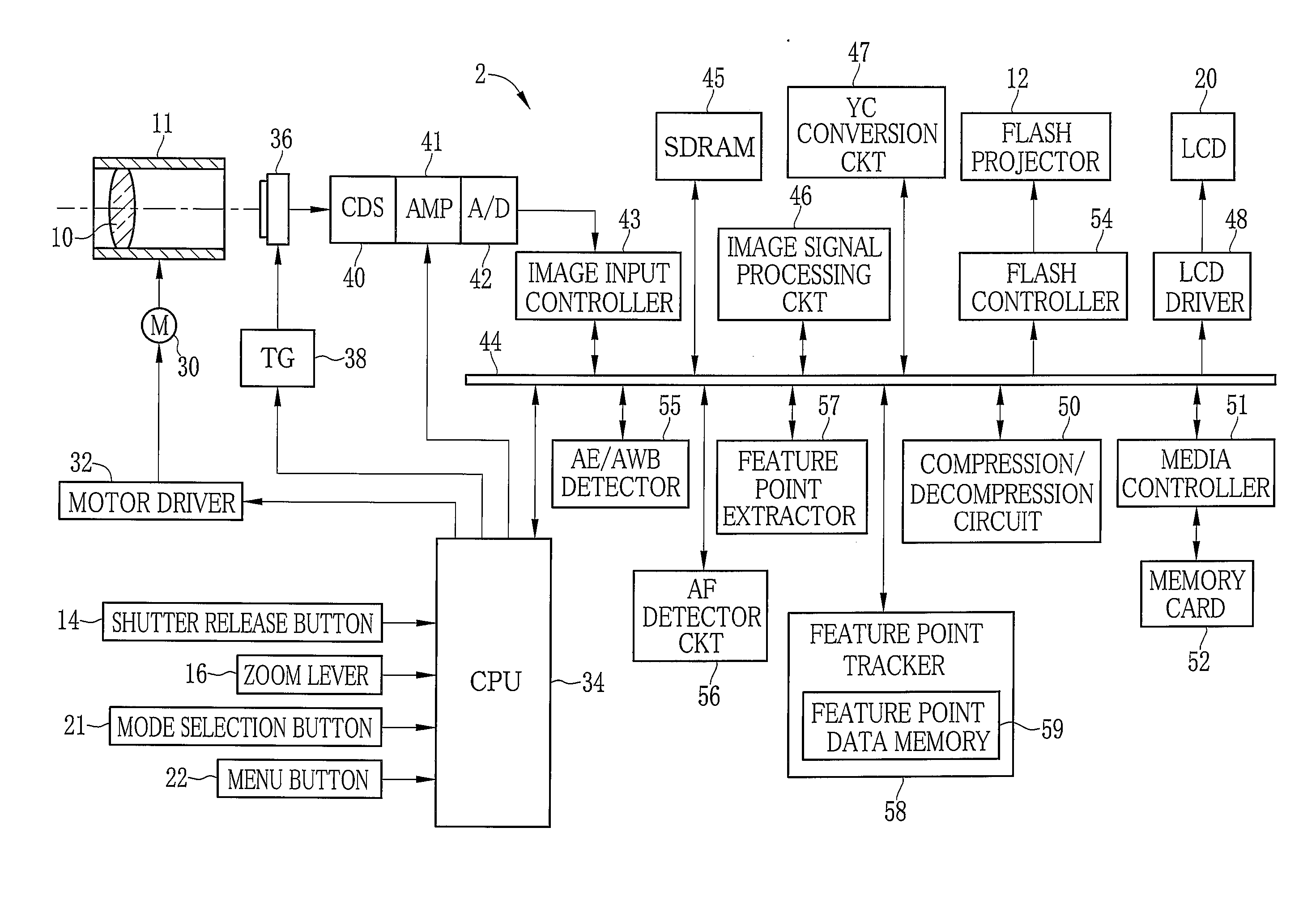
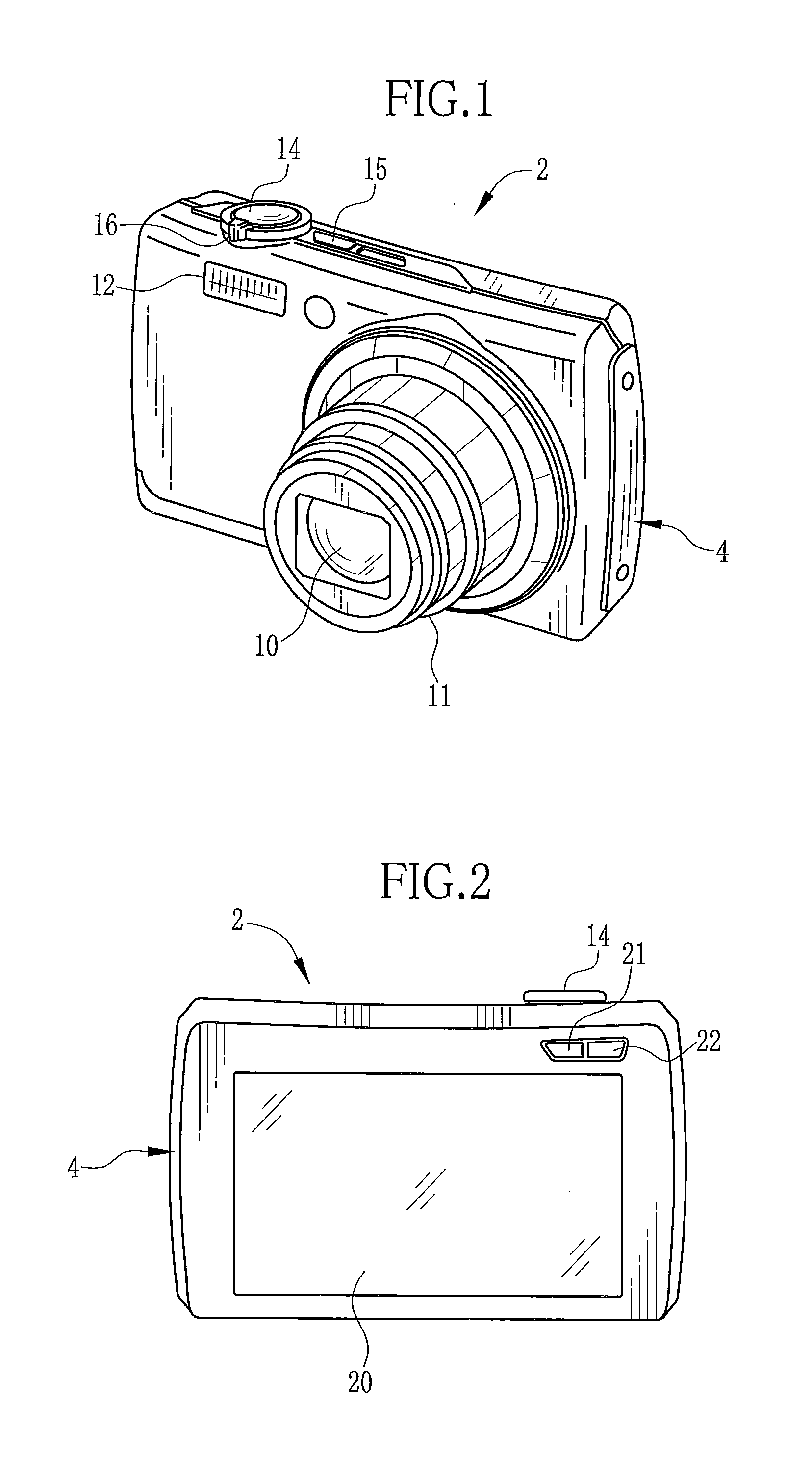
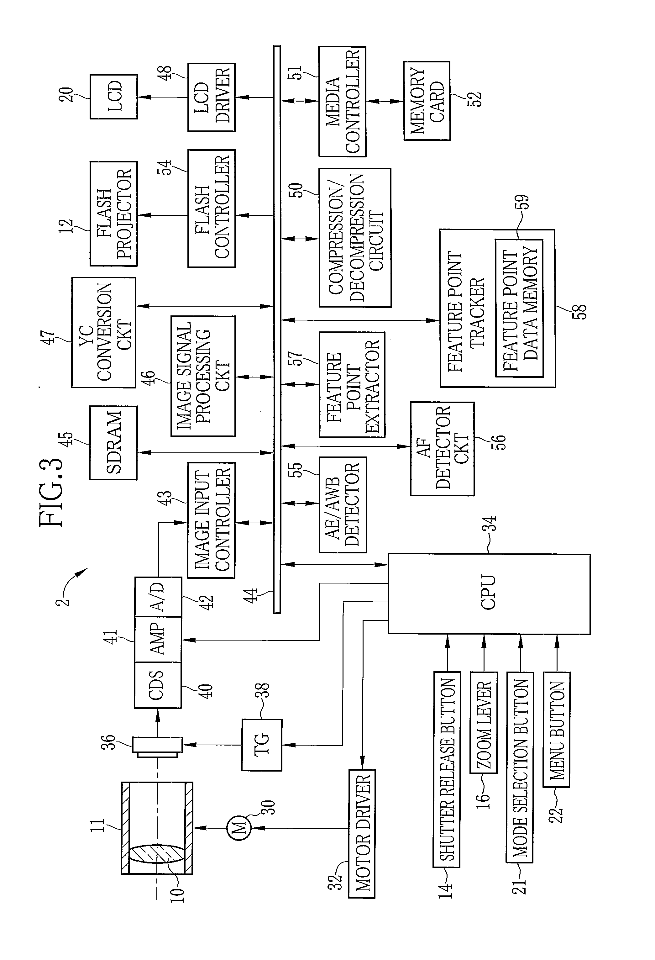
[0045]As shown in FIG. 1, a digital camera 2 (image display apparatus) 2 has a camera body 4 of a substantially rectangular prism shape. The camera body 4 has a front side provided with a lens barrel 11 holding a taking lens 10 therein, and a flash projector 12 for illuminating a subject. On a top side of the camera body 4 are provided a shutter release button 14 for giving an instruction to take a shot, a power button 15 for turning a power source ON and OFF, and a zoom lever 16 for zooming the taking lens 10 toward a wide-angle side or a telephoto side.

[0046]The shutter release button 14 is such a two-step switch that has a half-pressed position for causing the digital camera 2 to execute preparatory operations, such as auto-focusing (AF) and auto-exposure control (AE), to prepare for a shot. When the shutter release button 14 is farther pressed to a full-pressed position, the instruction to capture an image is given to the digital camera 2. Then the digital camera 2 converts an i...


PUM


Abstract

To track the movement of a common subject contained in a sequence of image frames time-sequentially captured by a digital camera, feature points of the subject are extracted from a first image frame, and corresponding points to the extracted feature point are identified in a second image frame that is captured after the first image frame. When the number of traceable feature points, to which the corresponding points can be identified, is less than a predetermined value, the speed of movement of the subject is judged high, and the shutter speed of the digital camera is set at a higher value.

Description

FIELD OF THE INVENTION[0001]The present invention relates to an imaging apparatus that detects movement of a common target object contained in a plurality of time-sequentially captured images on the basis of image data of these images. The present invention relates also to an image processing method.BACKGROUND OF THE INVENTION[0002]An imaging apparatus is known in the art that detects movement of a common target object or subject contained in a plurality of time-sequentially captured images by extracting several feature points of the subject from one of these images and then extracting corresponding feature points from other images to track these feature points.[0003]For example, JPA No. 2007-142507 discloses a teaching of extracting feature points from a sequence of images and calculating motion vectors of the extracted feature points, to correct image blurs by correcting image-clipping positions from the respective images and then averaging the clipped images. JPA No. 2007-183256 ...

Claims


Application Information

Patent Timeline
Patent Type & Authority Applications(United States)
IPC IPC(8): H04N5/228G06K9/00
CPCH04N5/232H04N23/60
Inventor SUGIMOTO, MASAHIKO
Owner FUJIFILM CORP
Learn More