
Bundled leaky transmission line, communication device, and communication system

a leaky transmission line and communication device technology, applied in waveguides, waveguide types, polarisation/directional diversity, etc., can solve the problem of limiting the location of leaky coaxial cables, difficult to arrange multiple leaky coaxial cables in arbitrary positions, and difficult to arrange multiple leaky coaxial cables with sufficient distance from each other

Inactive Publication Date: 2011-09-29
SONY CORP
View PDF7 Cites 24 Cited by
  • Summary
  • Abstract
  • Description
  • Claims
  • Application Information

AI Technical Summary

Benefits of technology

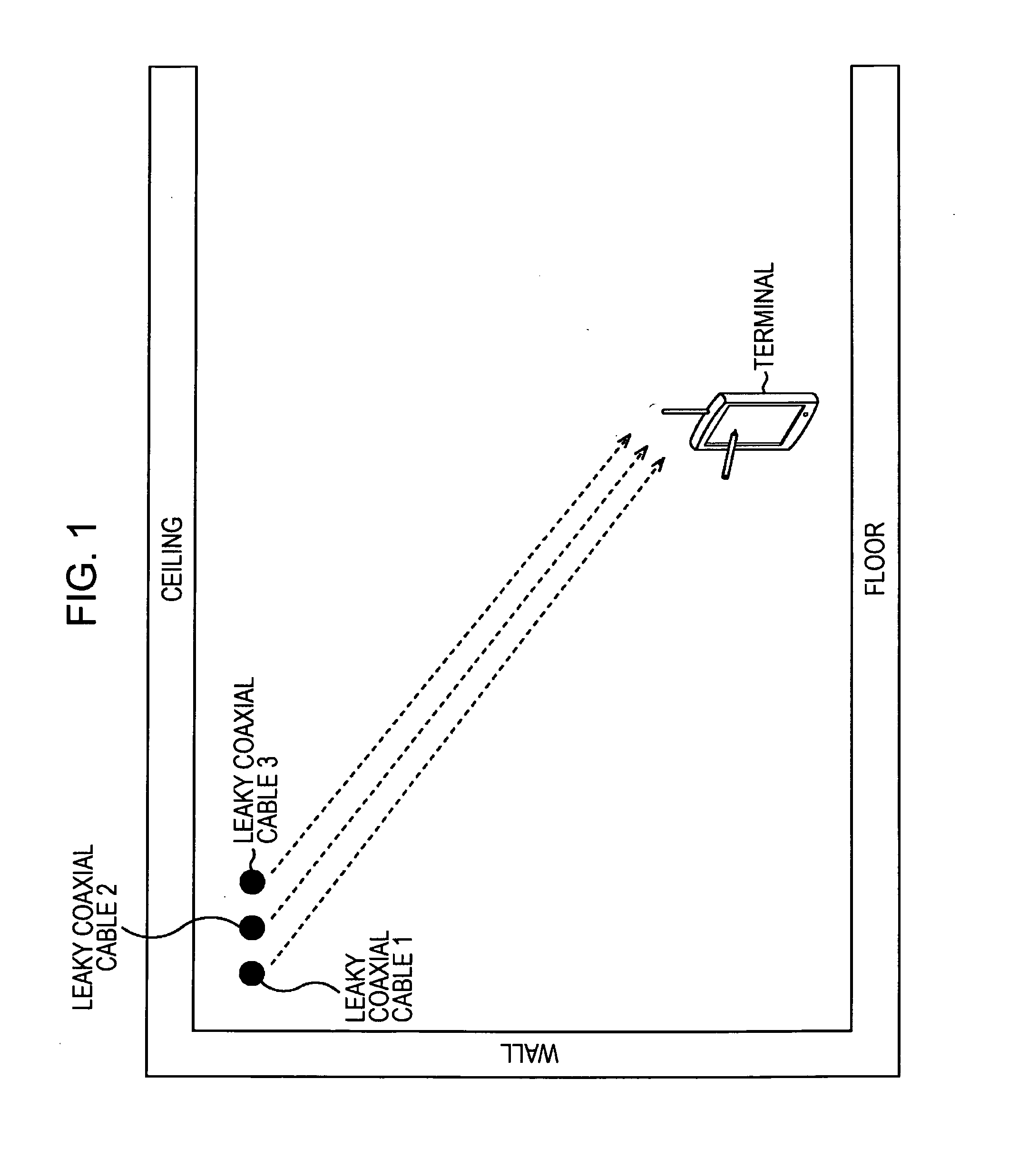
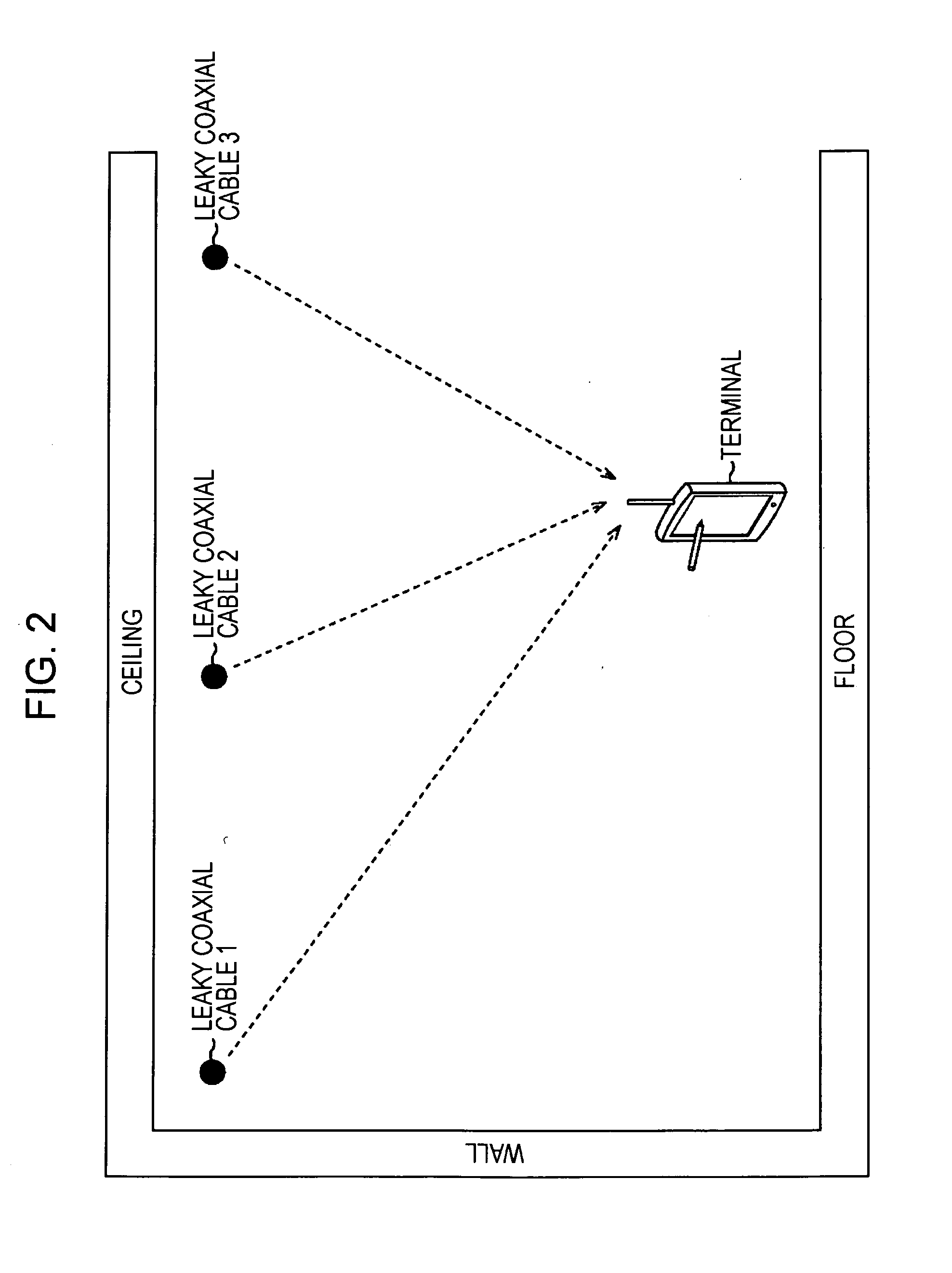
[0014]Further, for usage in MIMO (to sufficiently ensure the characteristic of MIMO), it is preferable to lower the correlation between branches (antennas) by setting the distance between antennas (between leaky coaxial cables) to λ / 2 or greater or causing polarized radio waves emitted from an antenna (leaky coaxial cable) to be orthogonal.
[0016]Thus, it is desirable to provide a leaky coaxial cable which sufficiently ensures the characteristic of MIMO and for which there are sufficient degree of freedom and easiness in installation.
[0028]According to the embodiments of the present invention, communication can be performed. Particularly, appropriate installation of multiple leaky transmission lines used as a MIMO antenna can be facilitated.

Problems solved by technology

However, in general, there are many limitations to the location of a leaky coaxial cable, and it has been difficult to arrange multiple leaky coaxial cables in arbitrary positions.
That is, depending on the space, it may have been difficult to arrange multiple leaky coaxial cables with sufficient distance from each other beyond the capacity of one cable rack, as shown in FIG. 2.
Also, preparing a new cable rack in order to locate the leaky coaxial cables sufficiently apart from each other not only leads to an increase in installation cost but also poses a risk of impairing the appearance of the space.
Therefore, when a leaky coaxial cable is installed in a space where the technical difficulty of installation is high or a leaky coaxial cable is installed by a person with poor knowledge regarding antennas, there has been a risk of impairing the characteristic of MIMO.

Method used


Image

  • Bundled leaky transmission line, communication device, and communication system
  • Bundled leaky transmission line, communication device, and communication system
  • Bundled leaky transmission line, communication device, and communication system

Examples


embodiment

1. Embodiment

Configuration of a Bundled Leaky Coaxial Cable

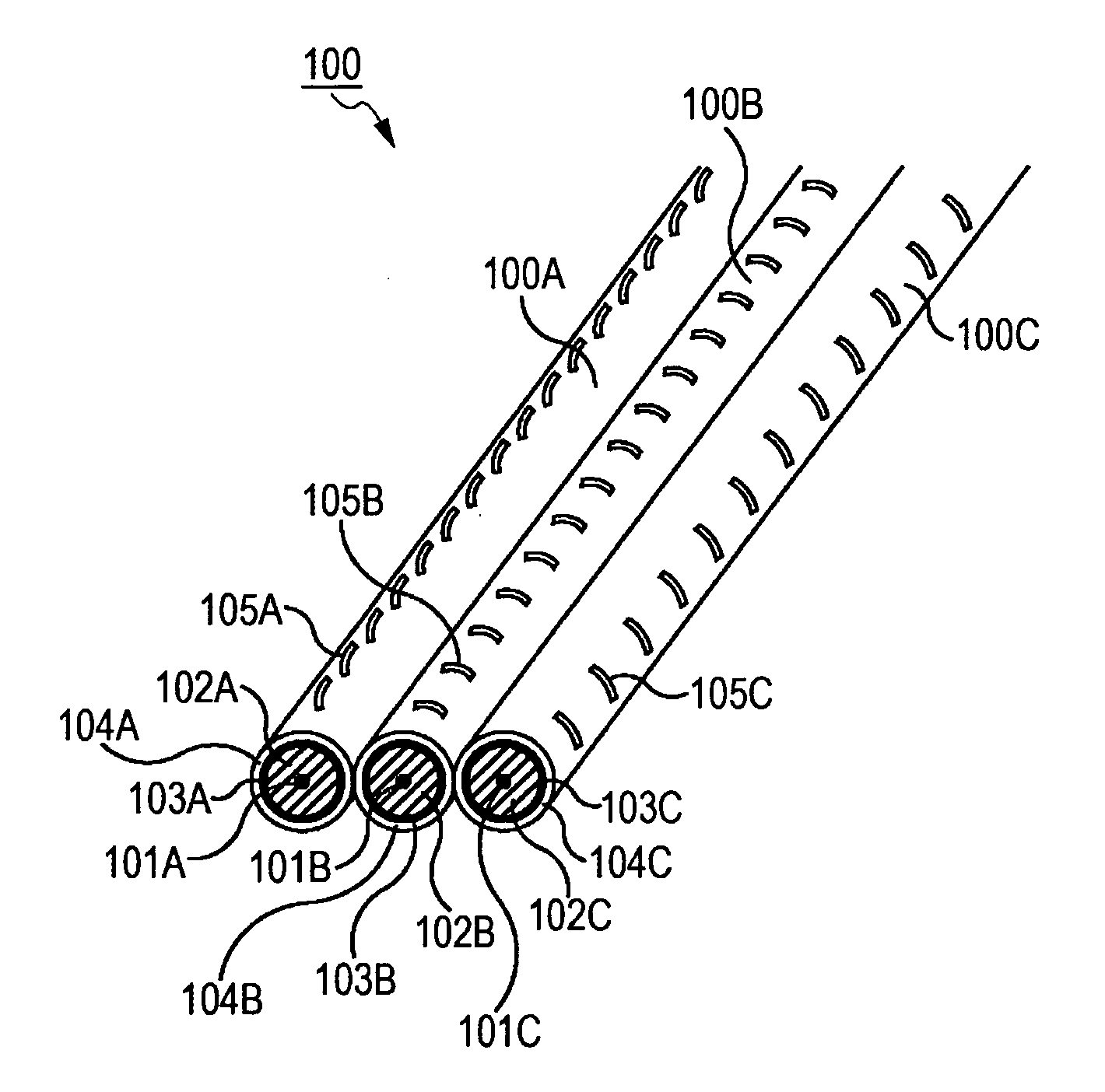
[0044]FIG. 3 illustrates a main configuration example of a bundled leaky coaxial cable according to an embodiment of the present invention.

[0045]A bundled leaky coaxial cable 100 shown in FIG. 3 is bound (bundled) in a state where an appropriate number of leaky coaxial cables are held together and is used as a multiple-input multiple-output (MIMO) antenna.

[0046]The MIMO refers to a wireless communication technique in which multiple antennas are combined to increase the bandwidth for data exchange. For example, applications include a high-speed wireless local area network (LAN).

[0047]In a normal wireless LAN communication, there has been a limit to the bandwidth such as, for example, 54 Mbps. However, in MIMO, different pieces of data are sent simultaneously with multiple antennas and synthesized at the time of reception to apparently increase the bandwidth for a high-speed communication. Theoretically, the apparent bandwidth...


PUM


Abstract

A bundled leaky transmission line includes a transmission line inside which a signal is transmitted, wherein multiple leaky transmission lines which exchange a radio wave mainly via a slit provided on an outer circumference of the transmission line are bundled, and the leaky transmission lines are bundled together such that the slit which is provided to each of the leaky transmission lines and which gives radio wave directionality to the leaky transmission line is directed in a direction different from each other.

Description

BACKGROUND OF THE INVENTION[0001]1. Field of the Invention[0002]The present invention relates to a bundled leaky transmission line, a communication device, and a communication system, and particularly relates to a bundled leaky transmission line, a communication device, and a communication system which can facilitate appropriate installation of multiple leaky transmission lines used as a MIMO antenna.[0003]2. Description of the Related Art[0004]Along with the spread of wireless local area networks (LANs) in recent years, there have been increasing demands to not only perform communication through a wireless area set with respect to a relatively small area such as a standard home but also perform communication through a wireless area set with respect to a broad range such as an office or a public facility.[0005]Measures to cover such a broad range with one access point generally include a method of increasing radio output of an access point or a terminal which performs communication ...

Claims


Application Information

Patent Timeline
Patent Type & Authority Applications(United States)
IPC IPC(8): H01Q13/22H01P3/00
CPCH01Q13/203H04B7/10H04B7/0413H01Q21/068
Inventor TAKAHASHI, HIROAKI
Owner SONY CORP
Learn More