Control apparatus and vehicle surrounding monitoring apparatus
a technology for monitoring apparatuses and control apparatuses, applied in scene recognition, television systems, instruments, etc., to achieve the effect of improving the usability of the vehicle surrounding the monitoring apparatus
- Summary
- Abstract
- Description
- Claims
- Application Information
AI Technical Summary
Benefits of technology
Problems solved by technology
Method used
Image
Examples
embodiment 1
[0035](Embodiment 1)
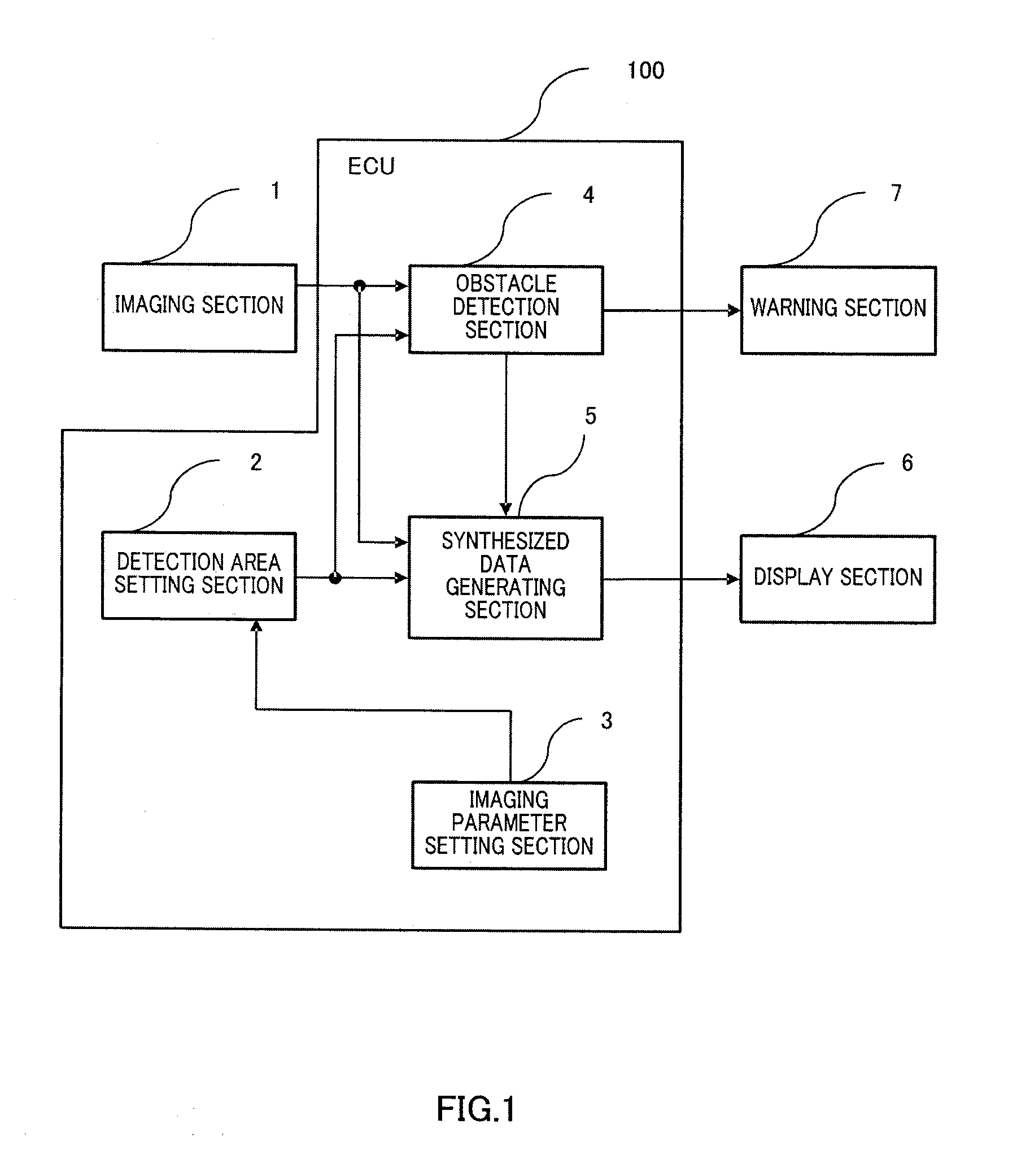
[0036]FIG. 1 is a block diagram showing a configuration of a vehicle surrounding monitoring apparatus according to embodiment 1 of the present invention.
[0037]The vehicle surrounding monitoring apparatus of FIG. 1 has an imaging section 1, a detection area setting section 2, an imaging parameter setting section 3, an obstacle detection section 4, a synthesized data generating section 5, a display section 5 and a warning section 7.
[0038]The imaging section 1, having one or a plurality of cameras installed in a vehicle, takes images of the surroundings of the vehicle and inputs data of photographed images (hereinafter “photographed data”) to the obstacle detection section 4 and synthesized data generating section 5. The kinds of cameras that can be used include CCD (Charge Coupled Device) cameras and CMOS (Complementary Metal Oxide Semiconductor) cameras.
[0039]In the following descriptions, the vehicle in which the imaging section 1 is installed in order to monitor...
embodiment 2
[0059](Embodiment 2)
[0060]The vehicle surrounding monitoring apparatus of embodiment 2 of the present invention will be described now. The vehicle surrounding monitoring apparatus of this embodiment has basically the same configuration as the above embodiment. Therefore, the same components as those of the above embodiment described earlier, will be assigned the same reference numerals and will not be described in detail.
[0061]The vehicle surrounding monitoring apparatus of the present embodiment has a configuration adding a detection area operation input section 201 to the configuration described in embodiment 1, as shown in FIG. 12. The detection area setting section 2, imaging parameter setting section 3, obstacle detection section 4, synthesized data generating section 5 and detection area operation input section 201 are implemented by executing a software program in an ECU 200 installed in the subject vehicle. The setting means is constituted by combining the detection area set...
embodiment 3
[0064](Embodiment 3)
[0065]The vehicle surrounding monitoring apparatus of embodiment 3 of the present invention will be described now. The vehicle surrounding monitoring apparatus of the present embodiment has basically the same configuration as the above embodiments. Therefore, the same components as those of the above embodiments described earlier, will be assigned the same reference numerals and will not be described in detail.
[0066]The vehicle surrounding monitoring apparatus of the present embodiment has a configuration adding a driving state information acquiring section 301 to the configuration described in embodiment 1, as shown in FIG. 14. The detection area setting section 2, imaging parameter setting section 3, obstacle detection section 4, synthesized data generating section 5 and driving state information acquiring section 301 are implemented by executing a software program in an ECU 300 installed in the subject vehicle. The setting means is constituted by combining the...
PUM
 Abstract
Description
Claims
Application Information
 - R&D
- Intellectual Property
- Life Sciences
- Materials
- Tech Scout
- Unparalleled Data Quality
- Higher Quality Content
- 60% Fewer Hallucinations
Browse by: Latest US Patents, China's latest patents, Technical Efficacy Thesaurus, Application Domain, Technology Topic, Popular Technical Reports.
© 2025 PatSnap. All rights reserved.Legal|Privacy policy|Modern Slavery Act Transparency Statement|Sitemap|About US| Contact US: help@patsnap.com


