
Unified Virtual Contiguous Memory Manager

a memory manager and virtualization technology, applied in the field of computing devices, can solve the problems of inconvenient operation, difficult if not practical, inability to runtime allocate large physical buffers in prior systems, and most certainly not satisfactory

Inactive Publication Date: 2011-09-15
QUALCOMM INNOVATION CENT
View PDF1 Cites 8 Cited by
  • Summary
  • Abstract
  • Description
  • Claims
  • Application Information

AI Technical Summary

Problems solved by technology

Moreover, runtime allocation of large physical buffers in prior systems is difficult if not practical.
Accordingly, current systems do not always operate in a convenient manner and will most certainly not be satisfactory in the future.

Method used


Image

  • Unified Virtual Contiguous Memory Manager
  • Unified Virtual Contiguous Memory Manager
  • Unified Virtual Contiguous Memory Manager

Examples


Embodiment Construction

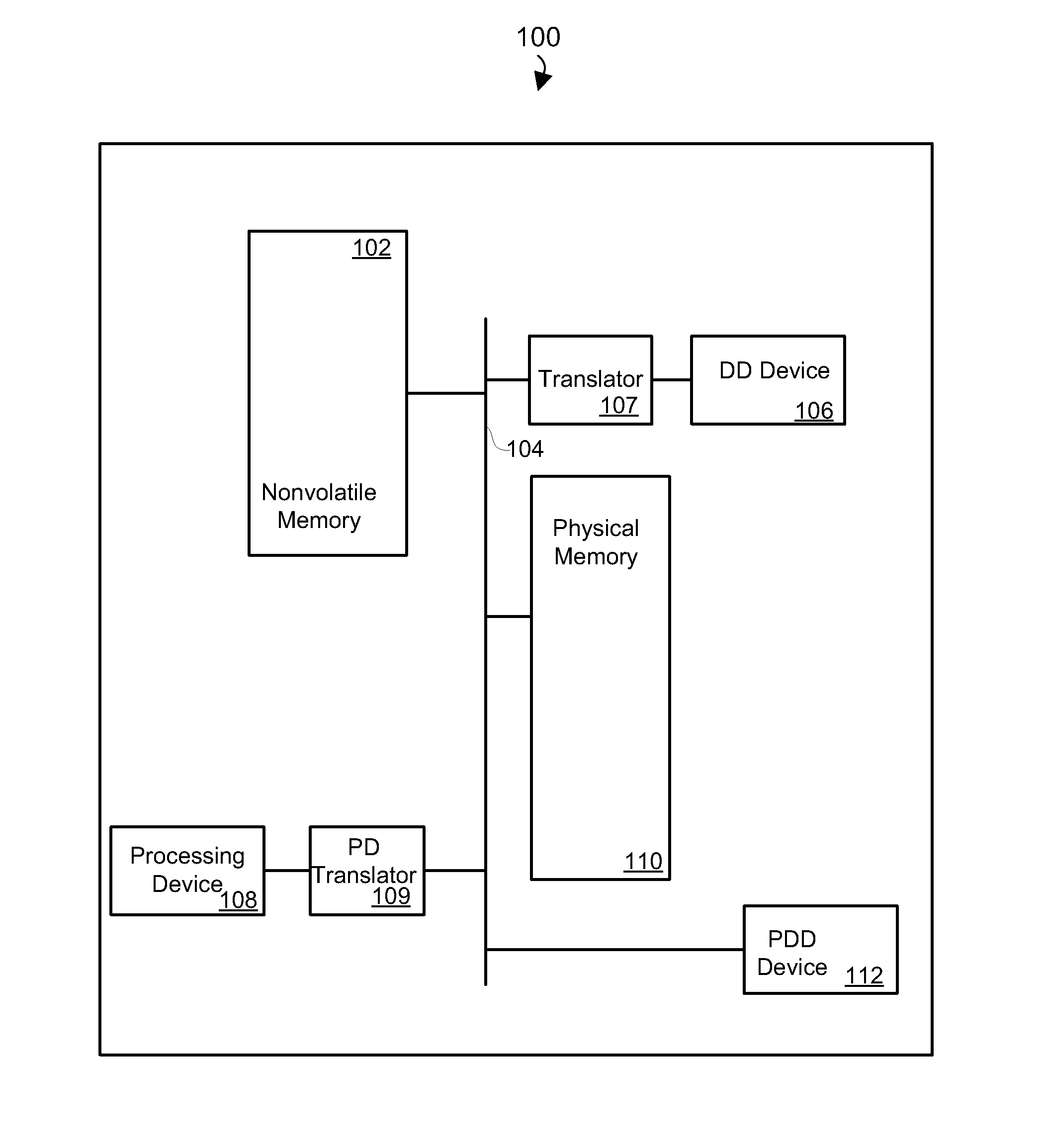
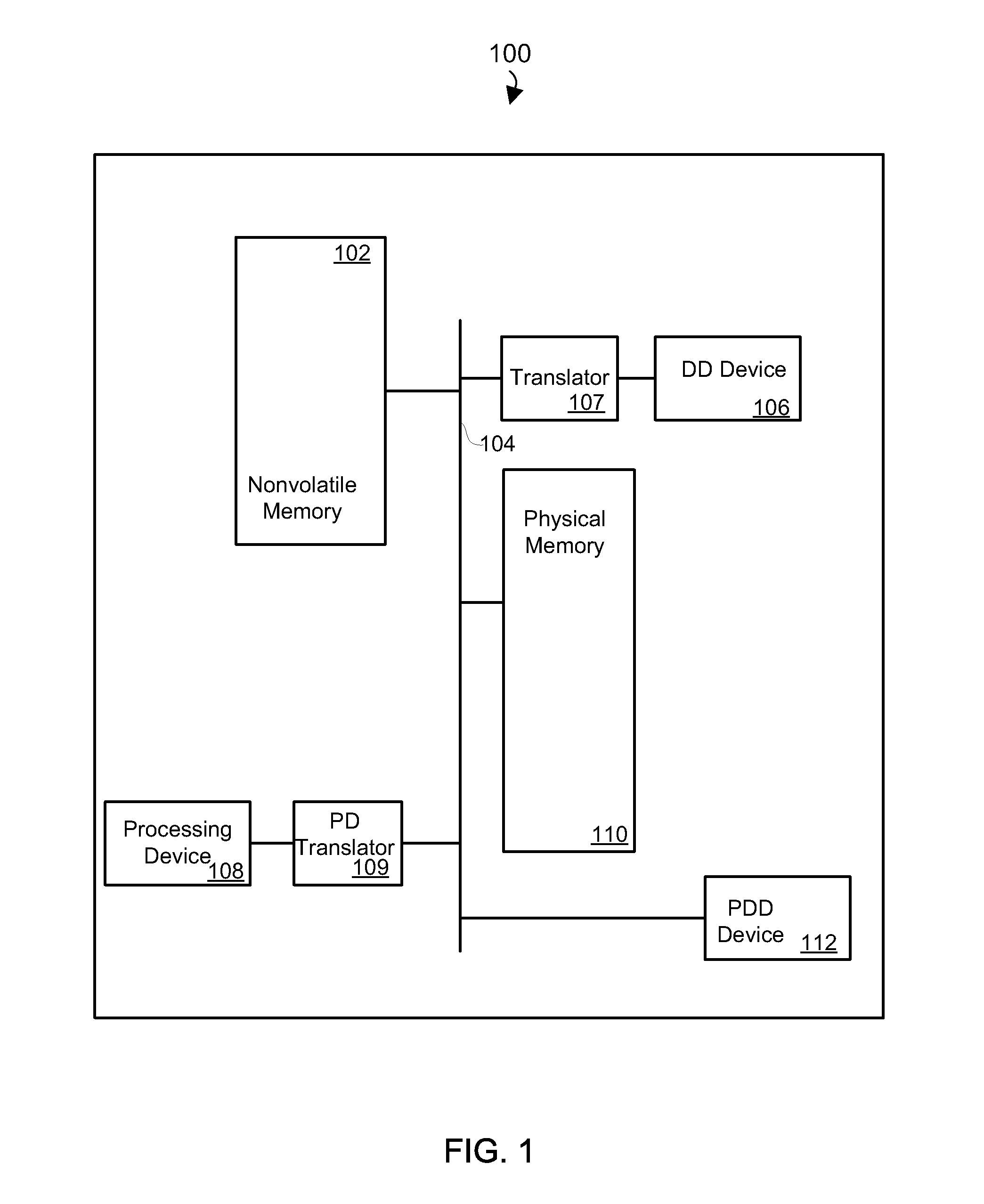
[0014]Referring first to FIG. 1, shown is a block diagram depicting physical components of an exemplary embodiment of a computing device 100. As shown, nonvolatile memory 102 is coupled to a bus 104 that is also coupled to a device-driver (DD) device 106 and a processing device 108 via corresponding translators 107, 109. In addition, a physical memory 110 and a physical-device-driver (PDD) device 112 (also referred to herein as a physically-mapped device) are also coupled to the bus 104. Although the components depicted in FIG. 1 represent physical components of the computing device 100, it is not intended to be an actual hardware diagram; thus many of the components depicted in FIG. 1 may be realized by common underlying constructs or distributed among additional physical components.

[0015]In addition, FIG. 1 represents a simplification of embodiments that may be used to realize the computing device in FIG. 1. For example, the PD device, PDD device and processing device 108 represen...


PUM


Abstract

Memory management methods and computing apparatus with memory management capabilities are disclosed. One exemplary method includes mapping an address from an address space of a physically-mapped device to a first address of a common address space so as to create a first common mapping instance, and encapsulating an existing processor mapping that maps an address from an address space of a processor to a second address of the common address space to create a second common mapping instance. In addition, a third common mapping instance between an address from an address space of a memory-management-unit (MMU) device and a third address of the common address space is created, wherein the first, second, and third addresses of the common address space may be the same address or different addresses, and the first, second, and third common mapping instances may be manipulated using the same function calls.

Description

FIELD OF THE INVENTION[0001]The present invention relates to computing devices. In particular, but not by way of limitation, the present invention relates to apparatus and methods for memory management in computing devices.BACKGROUND OF THE INVENTION[0002]Some computing devices (e.g., smart phones, PDAs, desktop and mobile computers, and mobile media devices) utilize a physical memory (PMEM) management API to allocate and free large buffers outside of an operating system (OS) heap. In these systems, however, attention must be paid to determine whether those buffers are virtually or physically mapped by devices, and in addition, management code must be tailored to work across different devices that may gain or lose I / O memory management units (IOMMUs). Moreover, runtime allocation of large physical buffers in prior systems is difficult if not practical. Accordingly, current systems do not always operate in a convenient manner and will most certainly not be satisfactory in the future....

Claims


Application Information

Patent Timeline
Patent Type & Authority Applications(United States)
IPC IPC(8): G06F12/10
CPCG06F12/109G06F12/1036
Inventor PFEFFER, ZACHARY A.BASSEL, LARRY A.
Owner QUALCOMM INNOVATION CENT
Learn More