
Atomic layer deposition chamber with multi inject

a technology of atomic layer deposition chamber and injector, which is applied in the direction of chemical vapor deposition coating, coating, electric discharge tube, etc., can solve the problems of large amount of ongoing effort, difficult deposition process, and localized thin spots on the substrate surfa

Active Publication Date: 2011-09-15
APPLIED MATERIALS INC
View PDF39 Cites 336 Cited by
  • Summary
  • Abstract
  • Description
  • Claims
  • Application Information

AI Technical Summary

Benefits of technology

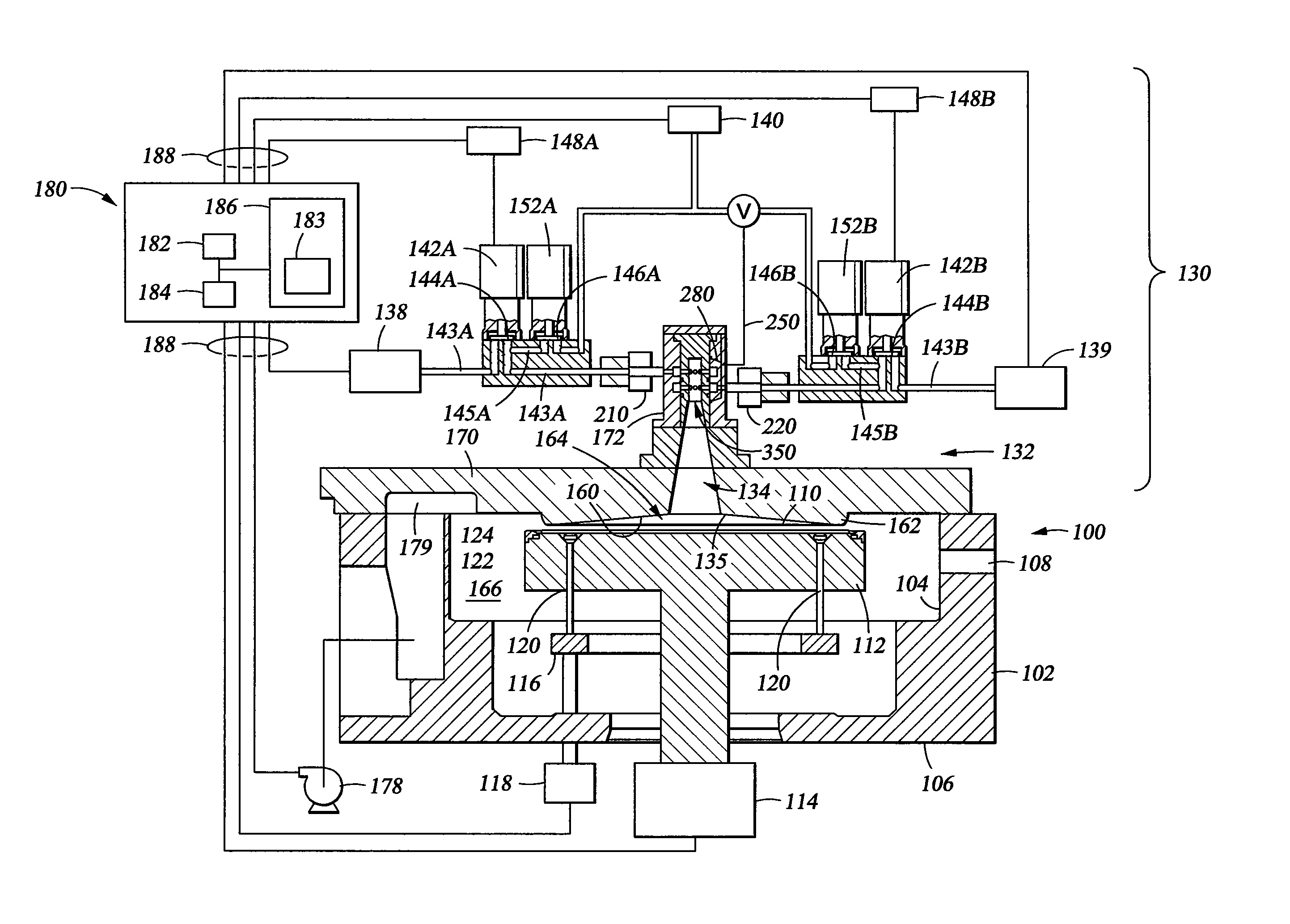
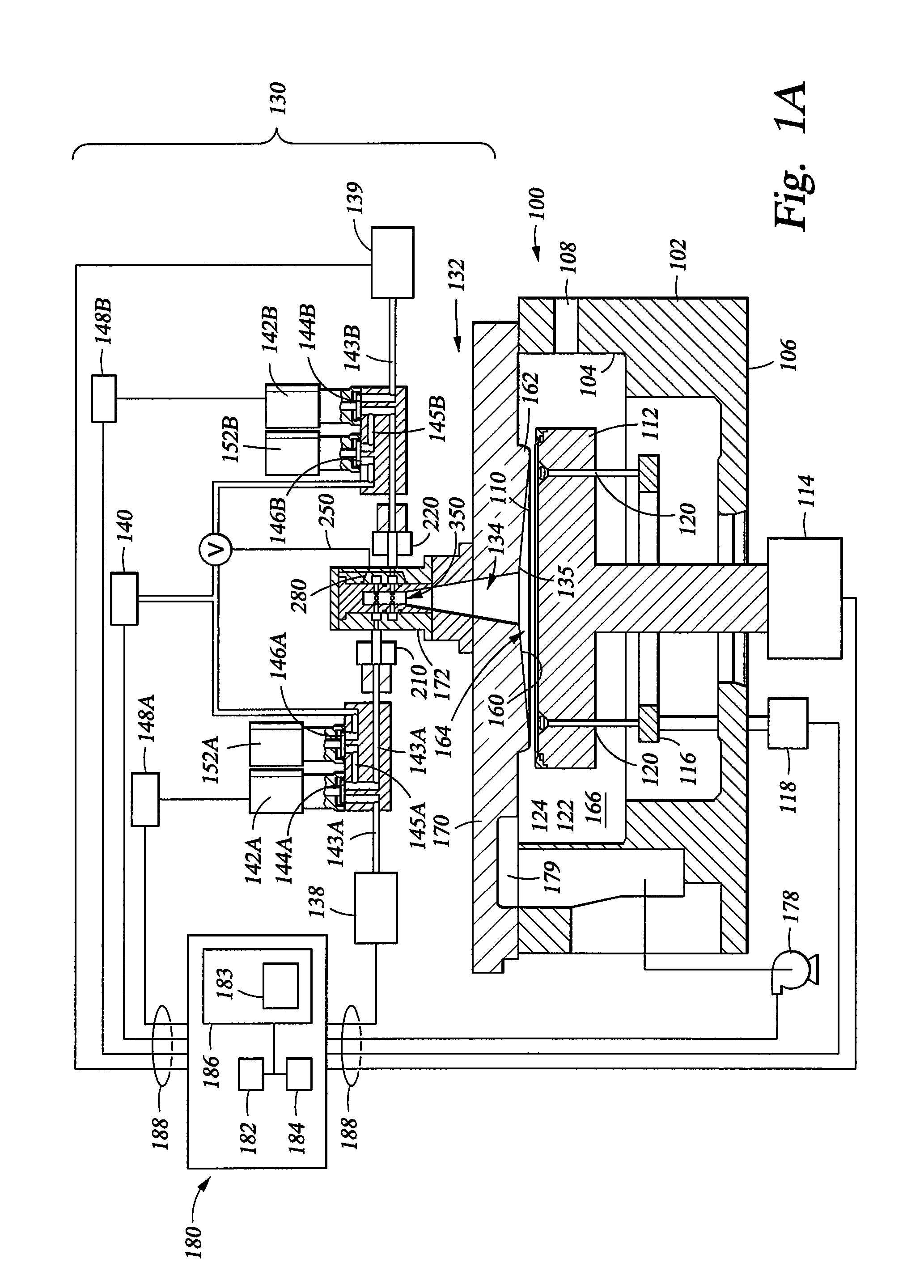
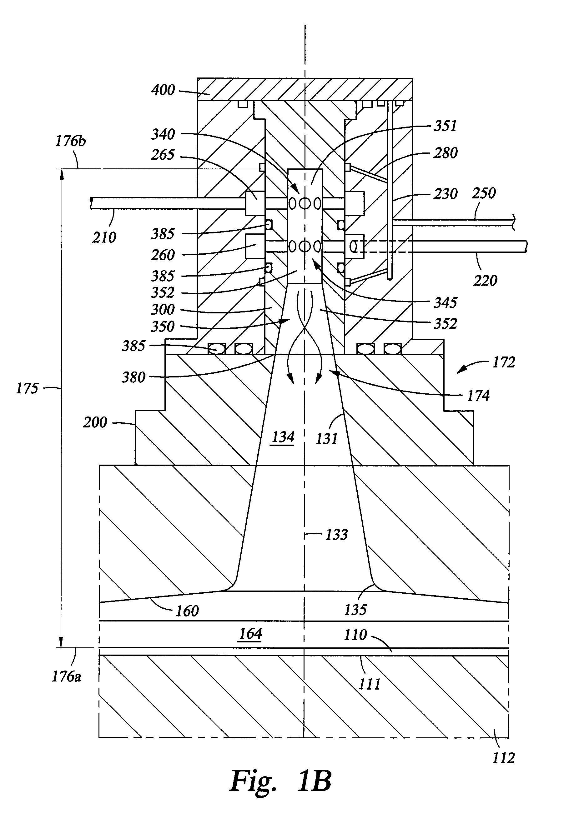
[0010]Embodiments of the invention relate to apparatus and methods for uniformly depositing materials on a substrate during an atomic layer deposition (ALD) process. In one embodiment, a chamber lid assembly comprises a channel having an upper portion and a lower portion, wherein the channel extends along a central axis, a housing having an inner region and at least partially defining two or more annular channels, an insert disposed in the inner region and defining the upper portion, the upper portion fluidly coupled with the two or more annular channels, and a tapered bottom surface extending from the bottom portion of the channel to a peripheral portion of the chamber lid assembly.
[0011]In one embodiment, a method for process

Problems solved by technology

However, as the fringes of circuit technology are pressed, the shrinking dimensions of interconnects in VLSI and ULSI technology have placed additional demands on the processing capabilities.
Many traditional deposition processes have difficulty filling submicron structures where the aspect ratio exceeds 4:1, and particularly where the aspect ratio exceeds 10:1.
Therefore, there is a great amount of ongoing effort being directed at the formation of substantially void-free and seam-free submicron features having high aspect ratios.
As monolayers of the first reactant and the second reactants are necessary for the formation of layer, it has been observed in some chamber designs for ALD processing that the gas flow from a conventional ALD chamber injection process does not provide a uniform annular gas flow, which results in localized thin spots on the substrate surface.

Method used


Image

  • Atomic layer deposition chamber with multi inject
  • Atomic layer deposition chamber with multi inject
  • Atomic layer deposition chamber with multi inject

Examples


Embodiment Construction

[0028]Embodiments of the invention provide apparatus and methods that may be used to deposit materials during an atomic layer deposition (ALD) process. Embodiments include ALD process chambers and gas delivery systems which include a multiple injection lid assembly. Other embodiments provide methods for depositing materials using these gas delivery systems during ALD processes. Examples of suitable processing chambers for incorporation of the apparatuses described herein include high k dielectric constant and metal ALD deposition chambers available from Applied Materials, Inc., of Santa Clara, Calif. The following process chamber description is provided for context and exemplary purposes, and should not be interpreted or construed as limiting the scope of the invention.

[0029]FIGS. 1A-1C are schematic views of one embodiment of a process chamber 100 including gas delivery system 130 adapted for ALD processes. FIG. 1D is a schematic view of process chamber 100 including another embodi...


PUM

PropertyMeasurementUnit
Angleaaaaaaaaaa
Angleaaaaaaaaaa
Angleaaaaaaaaaa

Abstract

Embodiments of the invention relate to apparatus and methods for depositing materials on substrates during atomic layer deposition processes. In one embodiment, a chamber lid assembly comprises a channel having an upper portion and a lower portion, wherein the channel extends along a central axis, a housing having an inner region and at least partially defining two or more annular channels, an insert disposed in the inner region and defining the upper portion, the upper portion fluidly coupled with the two or more annular channels, and a tapered bottom surface extending from the bottom portion of the channel to a peripheral portion of the chamber lid assembly.

Description

CROSS-REFERENCE TO RELATED APPLICATIONS[0001]This application claims benefit of U.S. Provisional Patent Application Ser. No. 61 / 313,573 (APPM / 015160L), filed Mar. 12, 2010, which is herein incorporated by reference.BACKGROUND OF THE INVENTION[0002]1. Field of the Invention[0003]Embodiments of the invention generally relate to apparatus and methods for atomic layer deposition. More particularly, embodiments of the invention relate to improved gas delivery apparatus and methods for atomic layer deposition.[0004]2. Description of the Related Art[0005]Reliably producing submicron and smaller features is one of the key technologies for the next generation of very large scale integration (VLSI) and ultra large scale integration (ULSI) of semiconductor devices. However, as the fringes of circuit technology are pressed, the shrinking dimensions of interconnects in VLSI and ULSI technology have placed additional demands on the processing capabilities. The multilevel interconnects that lie at...

Claims


Application Information

Patent Timeline
IPC IPC(8): C23C16/455C23C16/458
CPCC23C16/45504C23C16/45544C23C16/4408C23C16/45591C23C16/45574C23C16/45525C23C16/45561H01J37/32449H01L21/0228H01L21/28194H01L21/3141
Inventor YUDOVSKY, JOSEPHNGUYEN, ANH N.NGO, TAI T.
Owner APPLIED MATERIALS INC
Learn More