
Wall mounted assembly

Active Publication Date: 2011-09-15
MILLERKNOLL INC
View PDF6 Cites 20 Cited by
  • Summary
  • Abstract
  • Description
  • Claims
  • Application Information

AI Technical Summary

Benefits of technology

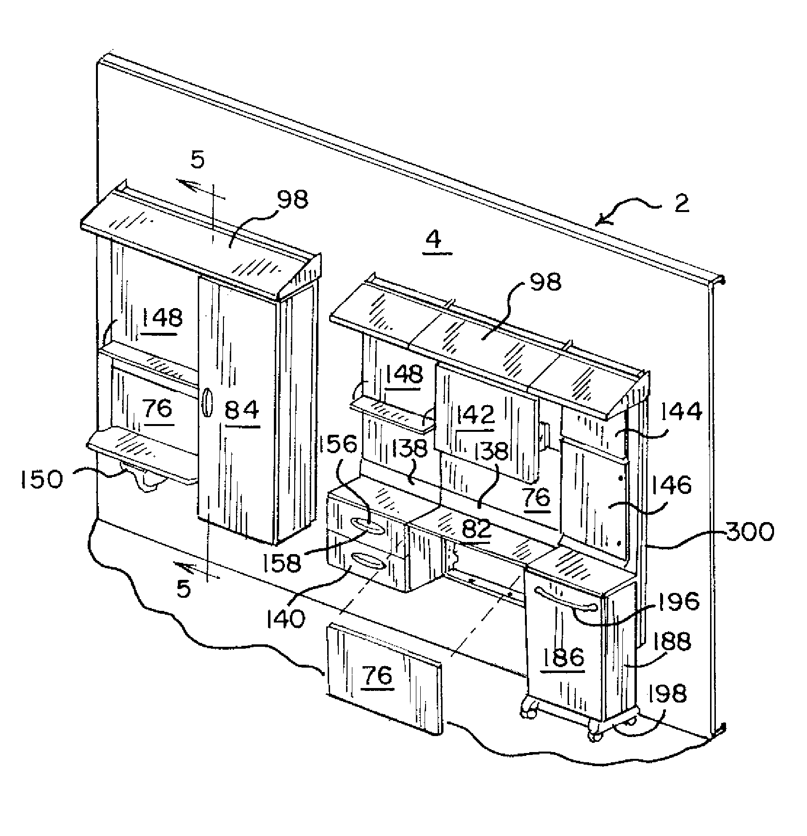
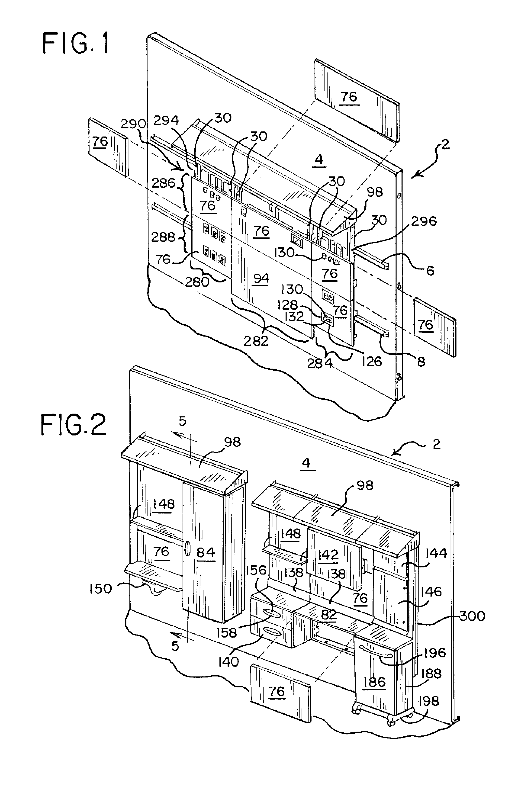
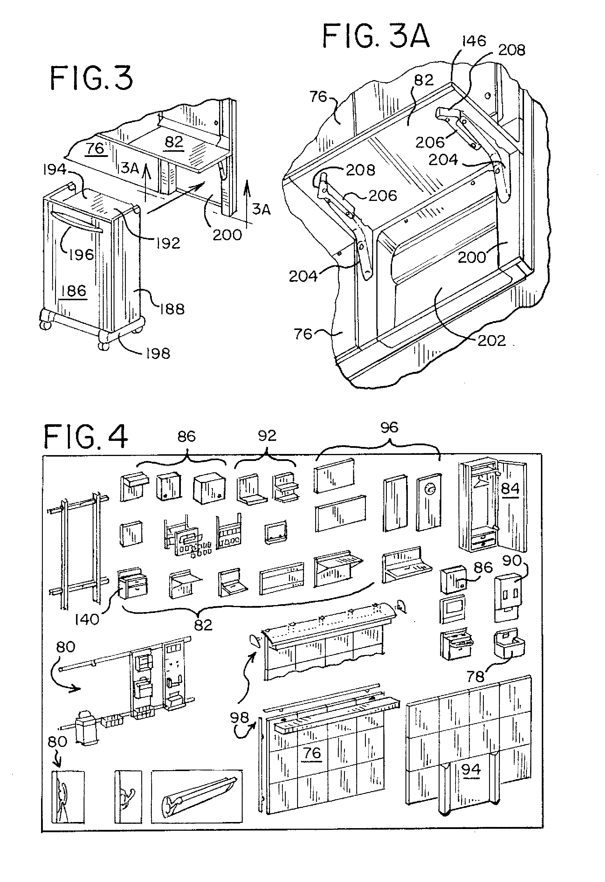
[0015]The various aspects and wall assembly embodiments, and methods for the use thereof, provide significant advantages over other wall assemblies. For example and without limitation, the system can be modular, with the interface components being quickly and easily reconfigured to provide different modules depending on desired configuration and / or environment of use. At the same time, the junctions between adjacent interface components, and the overall façade of the system, are virtually seamless, with any vertical or horizontal gaps penetrating to a backside of the interface components being essentially eliminated. In this way, the system is particularly well suited for healthcare environments. In particular, the monolithic and unitary façade prevents fluids and other contaminants, including bacteria, from penetrating the façade and becoming trapped in or between the stiles, rails and / or wall. Moreover, in the event of a spill or other contamination, the components can be easily cleaned without concern for penetration.
[0016]The system also provides for the position of each stile to be individually adjusted relative to the rail, both vertically and horizontally (laterally and longitudinally). In this way, the stiles can be appropriately positioned such that the interface components are properly positioned and aligned. In addition, the lateral adjustment device provides for the stiles to be preloaded against the wall, such that they are not loose. In addition, since the interface components making up any one module are interconnected, the entire module can be horizontally locked by way of securing a single stile, for example with a locking member. Likewise, one or more stiles can be configured with anti-dislodgment devices to prevent the system from being dislodged from the rail or rails.

Problems solved by technology

The rails, or components supported thereon, however, form various gaps or provide exposed surfaces, horizontal and vertical, in which fluids, dirt and other contaminants can accumulate.
The irregular surfaces and gaps may make cleaning and sanitization difficult.
In addition, such “open” systems, with exposed infrastructure, may not be aesthetically pleasing, and do not provide opportunities for routing or storing various utilities.
In addition, such systems typically lack any capability to adjust the vertical position of the components on the rails, or the lateral “in-out” position of the components relative to the wall.
While this may not be a problem when dealing with spaced apart individual components mounted to the rails, it may create an uneven appearance, present gaps and other areas for contaminant accumulation, and make the installation difficult when the components are positioned adjacent each other.

Method used


Image

  • Wall mounted assembly
  • Wall mounted assembly
  • Wall mounted assembly

Examples


Embodiment Construction

[0052]General Description:

[0053]It should be understood that the term “plurality,” as used herein, means two or more. The term “coupled” means connected to or engaged with whether directly or indirectly, for example with an intervening member, and does not require the engagement to be fixed or permanent, although it may be fixed or permanent. The term “first,”“second,” and so on, as used herein are not meant to be assigned to a particular component so designated, but rather are simply referring to such components in the numerical order as addressed, meaning that a component designated as “first,” may later be a “second” such component, depending on the order in which it is referred. It should also be understood that designation of “first” and “second” does not necessarily mean that the two components or values so designated are different, meaning for example a first component may be the same as a second component, with each simply being applicable to different components of the same...


PUM


Abstract

A wall assembly includes at least one horizontally extending rail having a rear surface adapted to engage the wall. A plurality of horizontally spaced and vertically extending stiles are coupled to the rail, with the stiles disposed forwardly of the rear surface of the rail. A plurality of interface components are coupled to the plurality of stiles. In various embodiments, the stiles may be interconnected to draw together adjacent interface components. The interface components also may include overlapping upper and lower edges. The stiles may be vertically and / or horizontally (laterally and longitudinally) adjustable relative to the rail. A lock member may be provided to secure at least one of the stiles to the rail. Various systems and methods of assembly and use are also provided.

Description

[0001]This application claims the benefit of U.S. Provisional Application Ser. No. 61 / 303,510, filed Feb. 11, 2010, the entire disclosure of which is hereby incorporated herein by reference.FIELD OF THE INVENTION[0002]The present invention relates generally to a wall assembly, and in particular to a wall mounted assembly, including for example a modular wall assembly for use in a healthcare environment.BACKGROUND[0003]Rooms are often configured with various user interface components, such as storage cabinets, shelving, worksurfaces and the like. In some settings, such as a healthcare environment, there also may be a need to provide an interface for various utilities, including water, gas, electrical and data outlets. Typically, rooms in such environments are configured with structural or architectural walls. In such environments, it may be desirable to mount the interface components to the structural walls so as to maximize the floor space for movement of various devices such as bed...

Claims


Application Information

Patent Timeline
IPC IPC(8): E04F19/00E04F19/08
CPCA47B95/008A47B96/067A47B96/06E03C1/181A47B97/001E03C1/00
Inventor BATES, MARKBOYCE, ANDREW J.KANG, CHUL MINKATJE, MICHAEL J.LYONS, SUSAN R.PORTER, KURT E.ROETMAN, JEFFREY D.SELLERS, PERRY L.ZACCAI, GIANFRANCO DINO
Owner MILLERKNOLL INC
Learn More