
Modular linking system, wheelchair kit and wheelchair

a module-based linking system and wheelchair technology, applied in the field of modular linking system, can solve the problems of reducing the flexibility and easy adjustment and replacement of the framework elements for changing the framework design, the head array system is not flexible enough to realize arbitrary designs, and the connection between the frame members is more complex

Active Publication Date: 2022-11-22
SUNRISE MEDICAL (US) LLC
View PDF14 Cites 0 Cited by
  • Summary
  • Abstract
  • Description
  • Claims
  • Application Information

AI Technical Summary

Benefits of technology

The system enables quick and easy reconfiguration, enhanced positioning capabilities, stronger locking forces, reduced part complexity, and integrated power / data distribution, minimizing external wire usage and improving operational efficiency.

Problems solved by technology

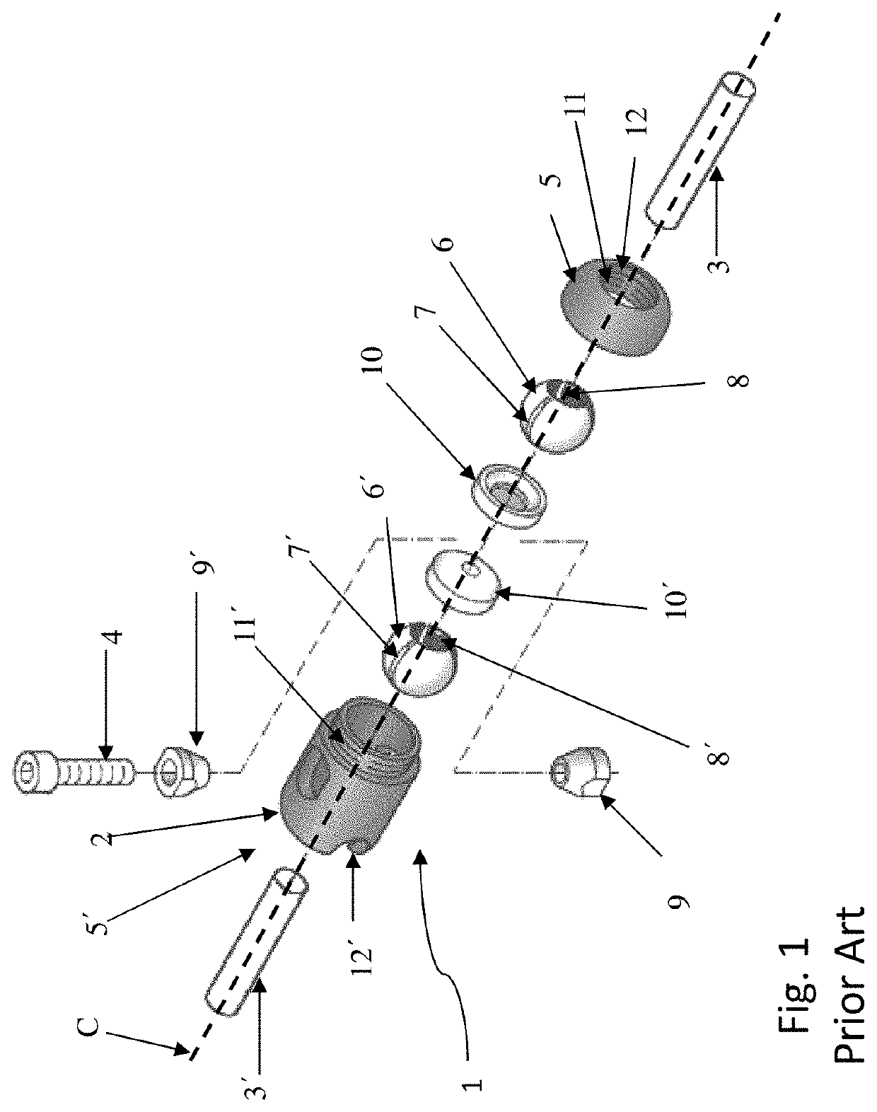
However, the connection between the frame members is more complex and lacks positioning and modification flexibility.
However, the framework elements are either screwed into the balls of the ball joints or are integrally formed with the balls, reducing the flexible and easy adjustment and replacement of the framework elements for changing the framework design.
However, the head array system is not flexible enough to realize arbitrary designs and cannot be easily reconfigured.
First, many modular linking systems cannot be mounted, dismounted or repositioned easily and quickly due to the sophisticated technical fastening means, requiring several steps and different tools to fulfill the task.
Second, when unlocking the linking modules in order to be able to position or orientate the links, there can be the risk that parts of the linking module or the linking module itself fall apart, getting lost, damaged, soiled and the like. Keeping several parts together also increases the efforts of reconfiguration.
Third, prior art modular linking systems have a limited positioning capability.
Fourth, the (un-)locking mechanism of prior art linking modules can become inaccessible or hardly accessible due to the fixed position or limited accession orientation capability of this mechanisms. This in turn increases the efforts of (un-)locking and hinders the quick and easy reconfiguration.
Fifth, realizing different forms or types of connections is not straightforward and routinely requires additional parts or completely different linking module designs. This increases the costs of such modular linking systems for the producer due to the need to produce more parts and different designs. It also increases the costs of the user because he needs to buy more parts and different designs to realize different forms and shapes. Additionally it also increases the burden of reconfiguration because all the different parts and design have to be not only in stock, but also on hand at the specific situation when wanting to reconfigure the form of the modular linking system. At last, changing parts and designs often require additional steps and different tools, making the reconfiguration harder and slower.
Sixth, the locking forces of existing systems are of limited strengths.
But the fastening means for the wires are often of a one-time use type, such that additional parts are needed.
Even more severe is the case when after reconfiguration, the length of the wires do not match with the new form of the modular linking system, making it inoperable or requiring again additional parts on hand.
External wires which are only loosely attached to the modular linking module, for example to allow a movement function, are also a source of tripping or getting caught or stuck.
This can lead to injuries or damages of the wires, up to making the equipment inoperable.

Method used


Image

  • Modular linking system, wheelchair kit and wheelchair
  • Modular linking system, wheelchair kit and wheelchair
  • Modular linking system, wheelchair kit and wheelchair

Examples


second embodiment

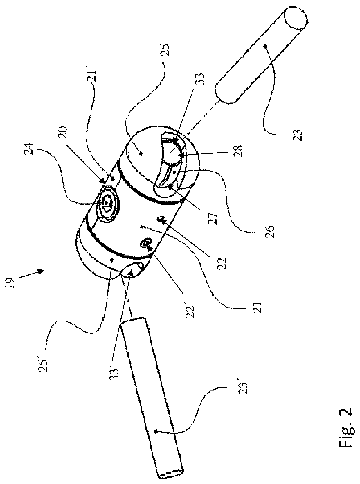
[0066]FIG. 5 shows a modular linking system of the present invention. The end caps 25, 25′ have a second opening 34, 34′ opposite a part of the first opening 33, 33′, with the openings 33, 33′; 34, 34′ allowing the rod 23, 23′ to pass both openings 33, 33′; 34, 34′ in order to provide a T-connection. The rods 23, 23′ therefore necessarily slide through the complete balls 26, 26′

third embodiment

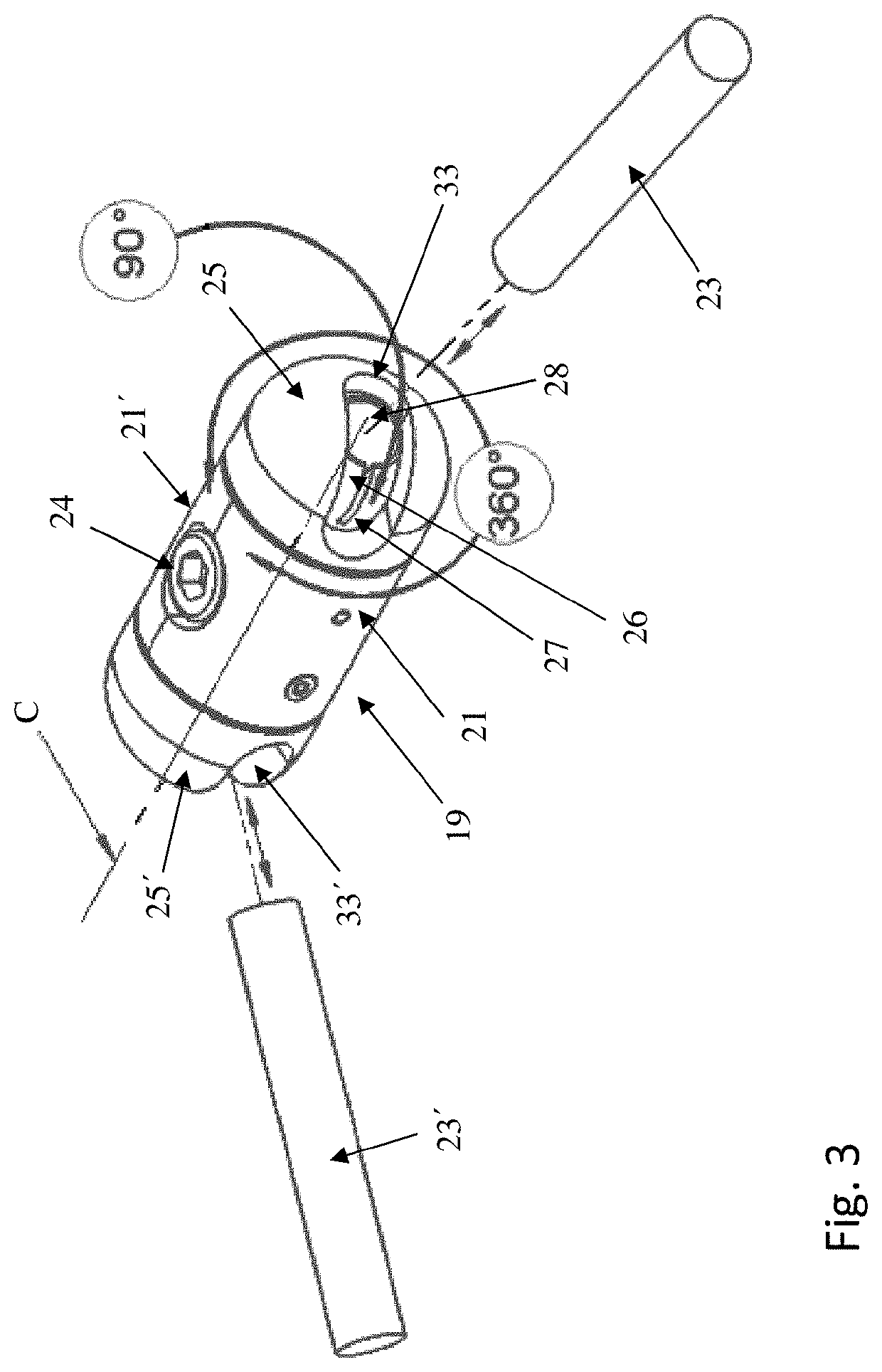
[0067]FIG. 6 shows a modular linking system according to the present invention. At least one of the shells 21, 21′ of one linking module 19 are replaced by star shells 32, 32′, forming a star linking module 31. Star shells 32, 32′ are adapted to also connect to at least one other linking module 19′ in place of a ball joint and offer therefore an additional axis C′, in particular an additional axis perpendicular to the center axis C. Every ball joint can be in principle replaced with a star module 31 to create additional axis. Star shells 32, 32′ can also be adapted to have more than one connection to other linking modules.

[0068]The star shells 32, 32′ are here shown to have a rectangular form. But of course the shape can be the same as the shells 21, 21′ while having protrusions matching at least in part the hook-type connection between end cap 25, 25′, shell 21, 21′ and module body 20. This allows the linking module 19′ to still rotate around the center axis C. Protrusions of a dif...


PUM


Abstract

A modular linking system provides a positioning and supporting structure for mounting various components, particularly on a wheelchair structure. A wheelchair kit includes such a modular linking system and further wheelchair includes at least one modular linking system or at least one wheelchair kit.

Description

CROSS-REFERENCE TO RELATED APPLICATIONS[0001]This application claims priority from European Patent Application No. 17 205 225.0 filed Dec. 4, 2017. The disclosure of this application is incorporated herein by reference in its entirety.BACKGROUND OF THE INVENTION[0002]The invention relates to a modular linking system for building up a structure to position and support various component, wheelchair kit comprising such a modular linking system and wheelchair with such a modular linking system. It refers in particular to a modular linking system with at least one linking module and at least one link to be connected therewith, wherein the linking module comprises a module body, a locking means, and at least one ball joint with a ball, wherein the ball has a slit and a central opening in form of a through hole along a center line, wherein the at least one link can be at least partly inserted into the central opening, and the locking means is adapted to releasably lock the orientation and ...

Claims


Application Information

Patent Timeline
Patent Type & Authority Patents(United States)
IPC IPC(8): F16C11/10F16M11/14F16M13/02A61G5/10F16M11/08F16M11/20A61G5/08
CPCF16C11/106A61G5/10F16M11/08F16M11/14F16M11/2014F16M11/2078F16M13/022A61G5/0875A61G5/0883A61G5/0891A61G5/1094A61G2203/20F16M2200/022
Inventor JOSTEN, JOHANNES ENGELMUNDUS LEONARDUS MATHIAS
Owner SUNRISE MEDICAL (US) LLC
Learn More