Optical Velocity Tracking for Paint Spray Gun

Active Publication Date: 2011-09-08
SOUTHWEST RES INST
View PDF11 Cites 13 Cited by
  • Summary
  • Abstract
  • Description
  • Claims
  • Application Information

AI Technical Summary

Problems solved by technology

If the spray gun is not properly operated, the result is a messy, unappealing, and ineffective paint job.
For example, if the standoff distance is too great or the painting velocity is too fast, the result is inadequate coverage of the surface.
If the standoff distance is too close or the painting velocity is too slow, the result is paint runs and wasted paint.

Method used


Image

  • Optical Velocity Tracking for Paint Spray Gun
  • Optical Velocity Tracking for Paint Spray Gun
  • Optical Velocity Tracking for Paint Spray Gun

Examples


Embodiment Construction

[0014]The following description is directed to a system and method for tracking and reporting velocity of a hand-held paint spray gun. The spray gun operator is provided with real time feedback of the velocity of the spray gun. This feedback information allows the operator to make immediate corrections of speed, ensuring optimal painting results. Wasted paint is lessened, and an adequate amount of coverage is ensured, while reducing the overall time spent painting.

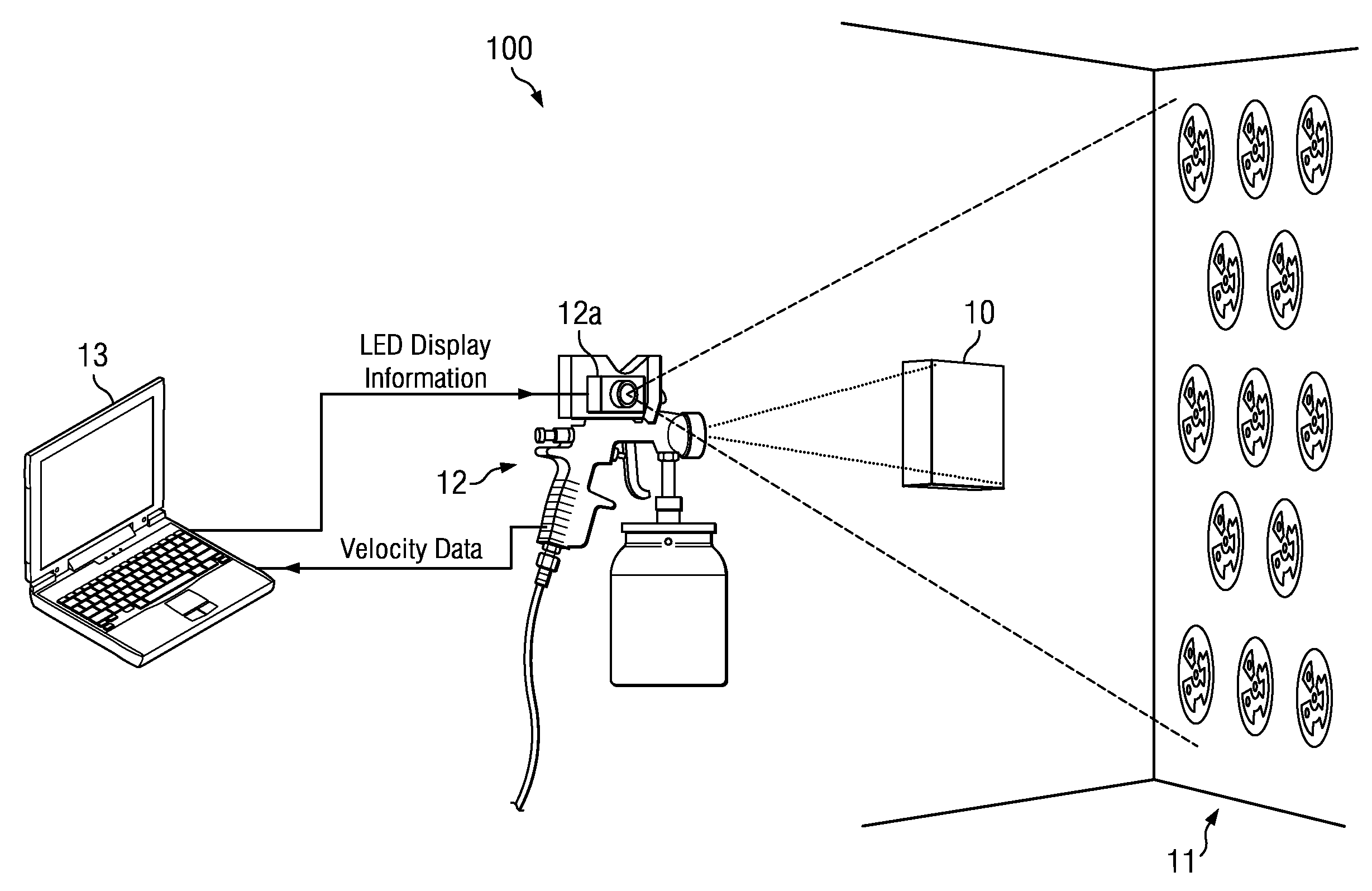
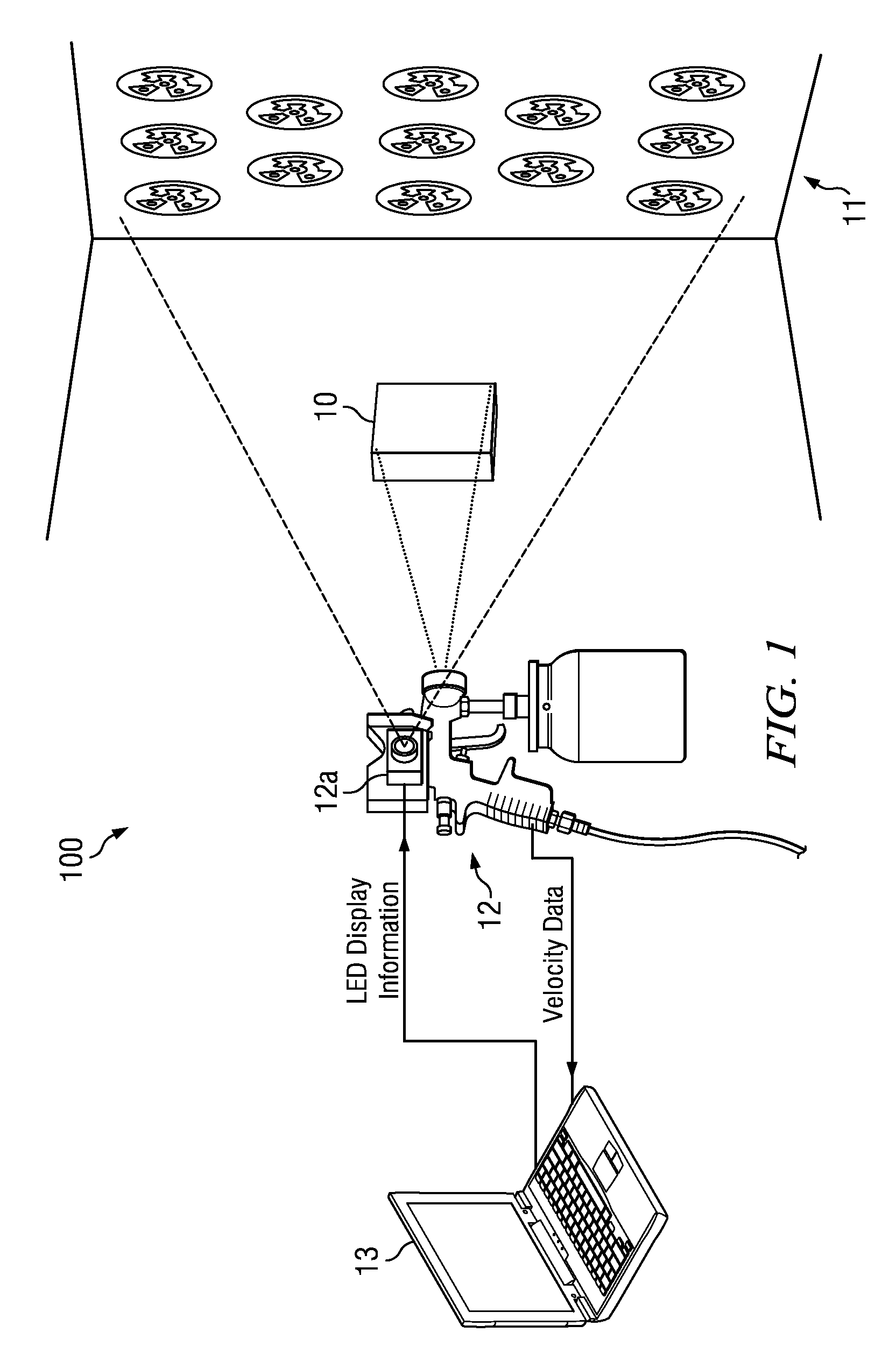
[0015]FIG. 1 illustrates the basic concept of a paint spray gun tracking system 100 in accordance with the invention. It should be understood that the term “paint” is used in a broad sense to include any kind of coating that may be sprayed upon the surface of an object, and can include various sealants, primers, etc.

[0016]The object 10 to be painted is located in a room having at least one fudicial wall 11. It should be understood that the number of fudicial walls 11 is related to the type of painting (or other coating) be...


PUM


Abstract

A method of tracking and reporting the velocity of a hand-held paint spray gun. The object to be painted is placed in a room having one or more fiducial walls. A camera is installed on the spray gun, with its field of view toward the one or more fiducial walls. As the object is painted, the camera detects fiducials, calculates their current position, and compares current positions to previous locations to determine movement and velocity. The current velocity is compared to a stored target velocity, and audible or visible feedback is provided to the spray gun operator.

Description

GOVERNMENT SUPPORT CLAUSE[0001]This invention was made with U.S. Government support under Contract No. SP4704-97-C-0004, awarded by the U.S. Army. The Government has certain rights in this invention.TECHNICAL FIELD OF THE INVENTION[0002]This invention relates to optical tracking systems and methods, and more particularly to an optical velocity tracking system and method for a paint spray gun.BACKGROUND OF THE INVENTION[0003]Paint spray guns are indispensible for large painting projects. Their use permits any object to be painted faster and without brushmarks. Paint spray systems use varying methods to atomize the paint (or other coating product), and allow for quick and even application of paint to the surface of the object to be painted.[0004]When using a paint spray gun, the spraying motion is somewhat of an art in itself. Ideally, the operator moves the gun at a constant velocity back and forth. Experts learn to push the spray button after the gun is up to speed, and to release t...

Claims


Application Information

Patent Timeline
IPC IPC(8): G06K9/00H04N7/18
CPCH04N7/18G06K9/00B05B12/004B05B12/126B05B12/084B05B7/02
Inventor THWING, CLINTON J.BARTLETT, JONATHAN D.LAICHE, ERIKA C.JONES, DAVID L.
Owner SOUTHWEST RES INST
Why Eureka
Try Eureka