
System and method for creating pseudo holographic displays on viewer position aware devices

a technology of viewer position awareness and display system, applied in the field of system and method, can solve problems such as misalignment, distortion and tilting

Inactive Publication Date: 2011-09-08
MARTIN JEAN PHILIPPE
View PDF18 Cites 37 Cited by
  • Summary
  • Abstract
  • Description
  • Claims
  • Application Information

AI Technical Summary

Benefits of technology

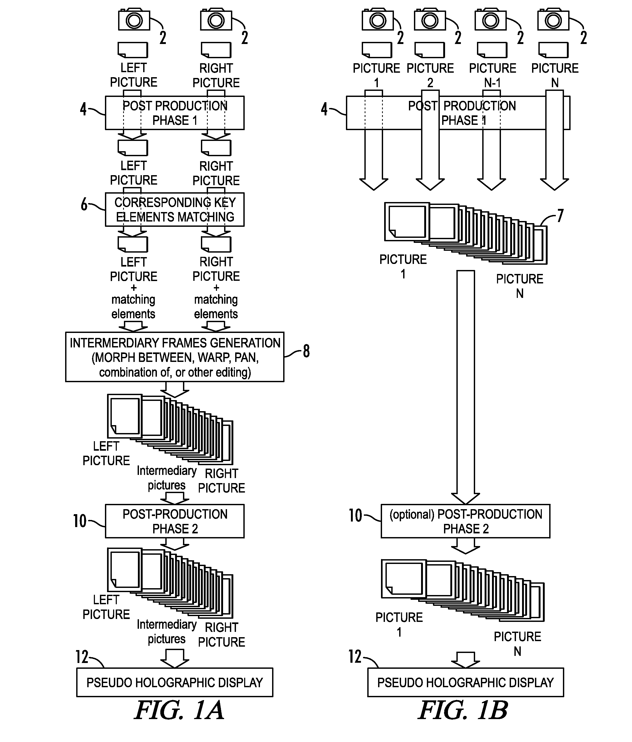
[0015]The present invention is capable of generating pseudo holographic images from real pictures that provide depth and volume perception with either a left to right movement of the smart phone device or when held at other angles. For devices that cannot move the relative position of the viewer to the display, the invention provides the depth and volume perception. The invention uses a process of matching elements in a pair of stereoscopic images, editing the images using the techniques of morphing, tweening and image warping among others to extrapolate an intermediary image which then further undergoes a post production phase of color correction, resizing etc. before being displayed as pseudo holographic image on a mobile device such as a smart phone, PDA, laptop computer, or stationary computer monitor.

Problems solved by technology

When more than one pair of stereo images or when concentric images are captured, misalignment, distortion and tilt may occur as well.

Method used


Image

  • System and method for creating pseudo holographic displays on viewer position aware devices
  • System and method for creating pseudo holographic displays on viewer position aware devices
  • System and method for creating pseudo holographic displays on viewer position aware devices

Examples


Embodiment Construction

[0034]The present invention uses a set of actual, or a set of actual and extrapolated images, to produce a pseudo holographic display. Referring now to FIG. 1(a), a flowchart of a preferred method of producing such a set of images for use in pseudo holographic display from stereoscopic images formed from cameras positioned at different viewing angles is shown. The method begins in step 2 with the capturing of a left side and right side image of an object from a pair of cameras. Alternatively, one camera can be used to capture images for both the left and right viewpoints. Once the images are captured, the method proceeds to the first post production phase in step 4. In the first post production phase 4, the acquired stereoscopic images undergo specific alterations to produce the desired final images. The processing procedures in the first post production phase are preferably standard photography post-production procedures such as smoothing the skin of a person, adjusting colors and ...


PUM


Abstract

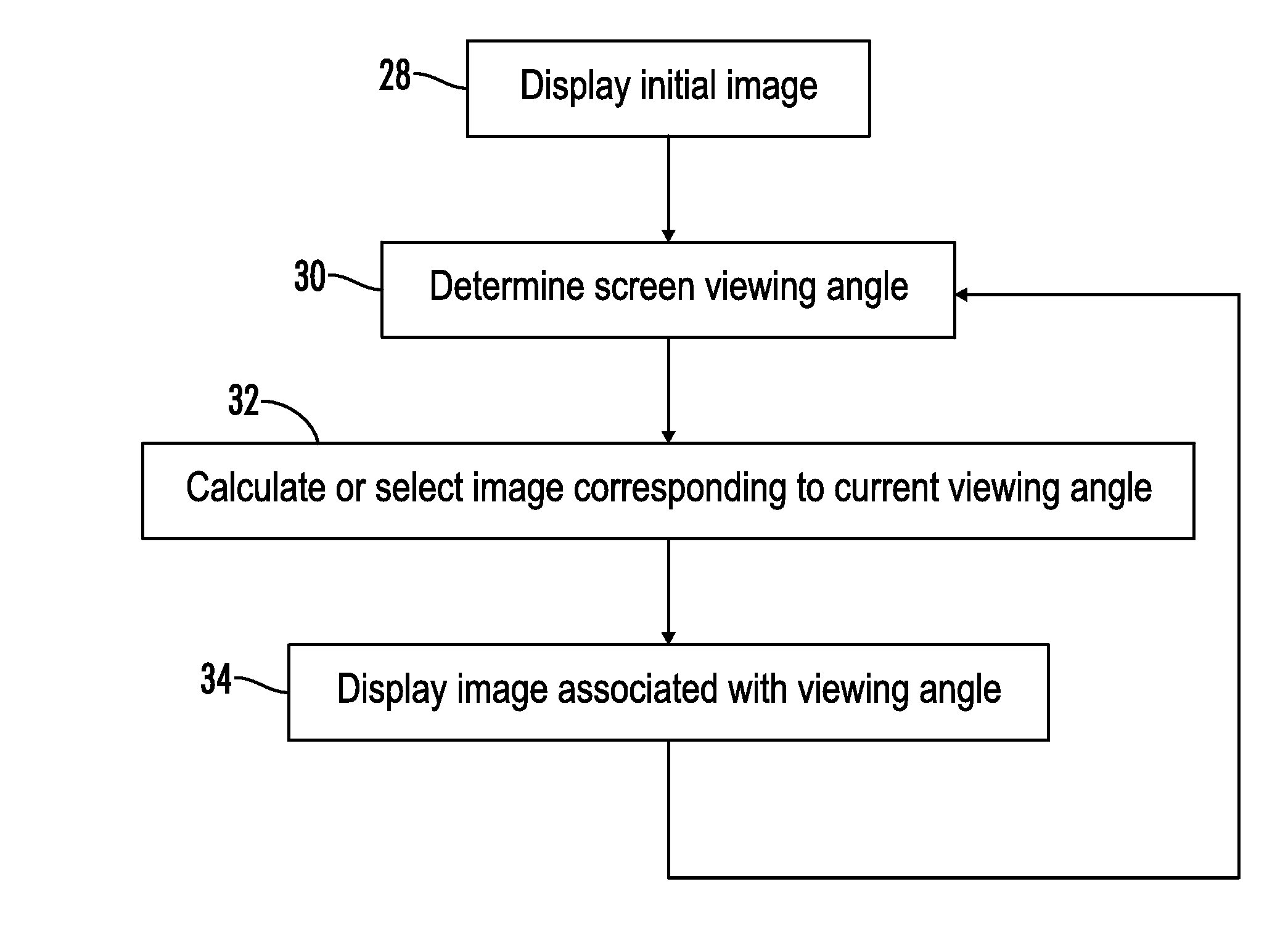
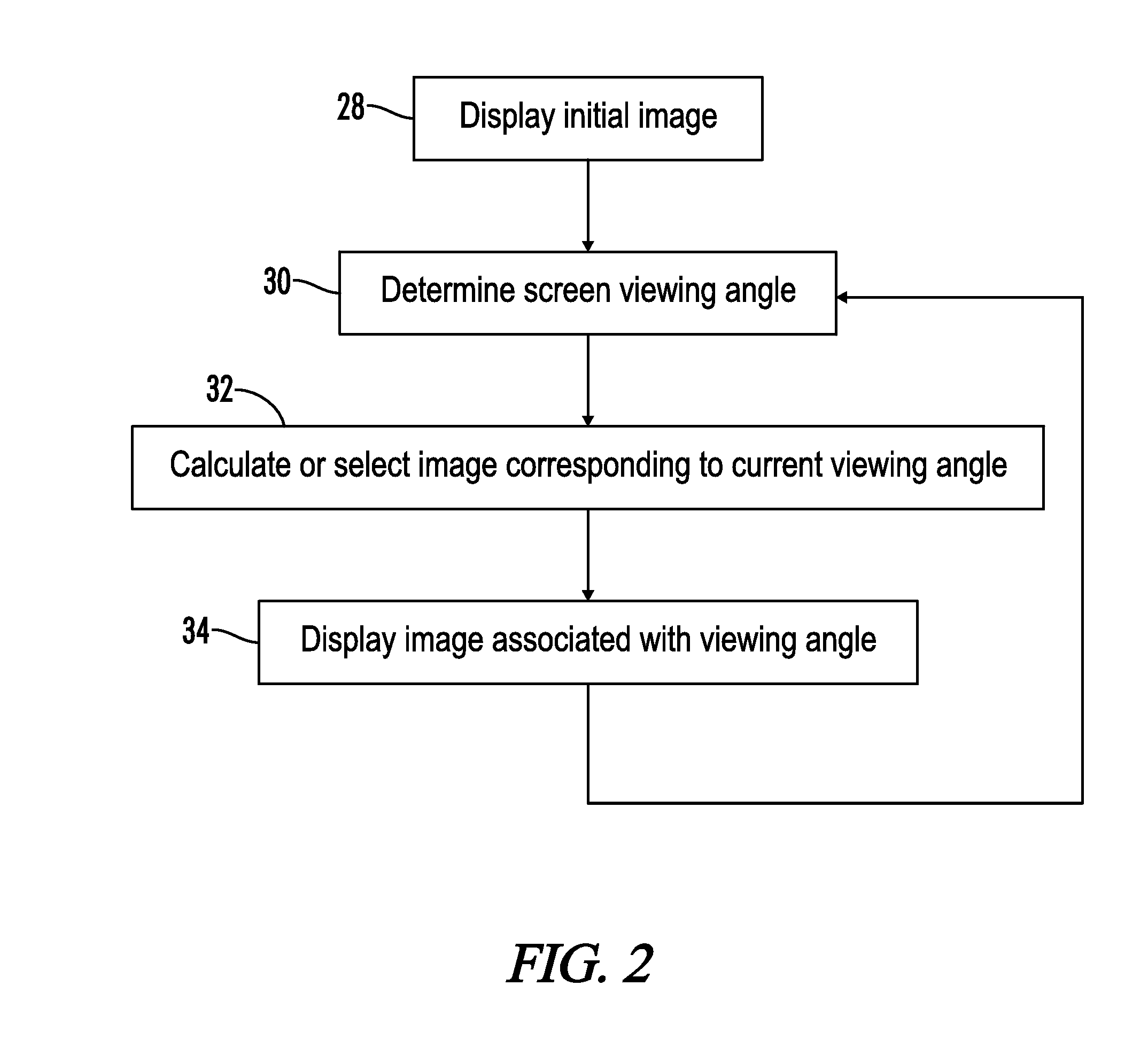
A pseudo holographic visual effect is produced by acquiring at least two actual images of a subject wherein each image represents a different viewing angle of the single subject. Intermediary images corresponding to other viewing angles of the subject may be extrapolated from the two actual images or two adjacent images if a sufficient number of actual images are not available to create the desired level of resolution. To create the effect, an initial start image is displayed. Computer based sensors or camera images from a camera are then used to determine any movement of the device or user from the initial position at which the initial image was displayed. Once movement is detected or once the position of the viewer is determined, the initial image is replaced with an image that corresponds to the change in the detected viewing angle or with an image that corresponds to the viewing angle of the viewer. This creates a pseudo holographic effect whereby the orientation of subject of the image appears to remain fixed despite the display or the viewer being moved. Additional layers for the image can be created by acquiring images of a background separately, creating a set of images that correspond to different viewing angles of the background and overlaying the background images with subject images during display.

Description

CROSS-REFERENCES TO RELATED APPLICATIONS[0001]The present application claims priority from co-pending U.S. Provisional Patent Application Ser. No. 61 / 240,394 filed Sep. 8, 2009.STATEMENT REGARDING FEDERALLY SPONSORED RESEARCH OR DEVELOPMENT[0002]Not Applicable.REFERENCE TO SEQUENCE LISTING OR COMPUTER PROGRAM LISTING APPENDIX[0003]Not Applicable.FIELD OF THE INVENTION[0004]The present invention relates generally to the display of holographic images. More particularly, the invention relates to a system and method for the production and display of pseudo holographic images generated from stereoscopic natural and synthetic images, or from photographs taken with multiple cameras set up to point concentrically towards the subject photographed, on viewer position aware devices such as cell phones, PDA's, computer monitors etc.BACKGROUND OF THE INVENTION[0005]The three dimensional (3D) display of images using the technique of stereoscopy is well known in the art. The stereoscopic viewing o...

Claims


Application Information

Patent Timeline
Patent Type & Authority Applications(United States)
IPC IPC(8): H04N5/89
CPCH04N5/89G03H1/2249
Inventor MARTIN, JEAN-PHILIPPE
Owner MARTIN JEAN PHILIPPE
Learn More