Spectacle Lens and Method for Designing the Same

Inactive Publication Date: 2011-09-01
HOYA LENS MFG PHILIPPINES
View PDF11 Cites 16 Cited by
  • Summary
  • Abstract
  • Description
  • Claims
  • Application Information

AI Technical Summary

Benefits of technology

[0022]The wearer can therefore readily look at a near object in binocular vision without eye fatigue. Further, since it is not necessary to change the size of the near region, the spectacle lens is highly useful for the spectacle wearer without decrease in area that can be used for near vision. Moreover, since the advantageous effects described above can be readily achieved by adjusting the spherical equivalent power on both sides of the point described above in the horizontal direction, no cumbersome step required in related art is necessary, such as a step of measuring deviation of the dominant eye.
[0023]In a preferred configuration, the spectacle lens of the aspect of the invention further includes, in addition to the near region, a far region corresponding to far vision and having power smaller than the power in the near region and an intermediate region corresponding to intermediate vision and having power continuously changing from the power in the far region to the power in the near region.
[0024]In this configuration, a progressive-power spectacle lens that can achieve the advantageous effects described above can be provided.
[0025]In a preferred configuration, the spectacle lens of the aspect of the invention further includes, in addition to the near region, an intermediate region corresponding to intermediate vision and having power smaller than the power in the near region.
[0026]The thus configured progressive-power spectacle lens can be a progressive-power spectacle lens for near-near vision (dedicated to near and intermediate vision) that can achieve the advantageous effects described above.
[0027]In a spectacle lens for near and far vision as a preferred configuration, near and intermediate vision, or near-near vision, the point described above is preferably a progressing end point positioned at the boundary between the near region and the intermediate region or a near dioptric power measuring point, which is the center of the near region.

Problems solved by technology

That is, in the near region of each of the spectacle lenses in Example 1 of related art, since the spherical equivalent power has the same value on the right and left sides of the near dioptric power measuring point NP on the principal line of fixation, the power of accommodation of the right eye differs in magnitude from that of the left eye depending on whether a target portion to be viewed is in front of the right eye or the left eye, resulting in ocular fatigue.

Method used


Image

  • Spectacle Lens and Method for Designing the Same
  • Spectacle Lens and Method for Designing the Same
  • Spectacle Lens and Method for Designing the Same

Examples


first embodiment

[0056]FIGS. 1 to 5 show the invention.

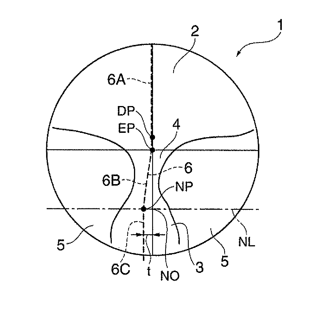
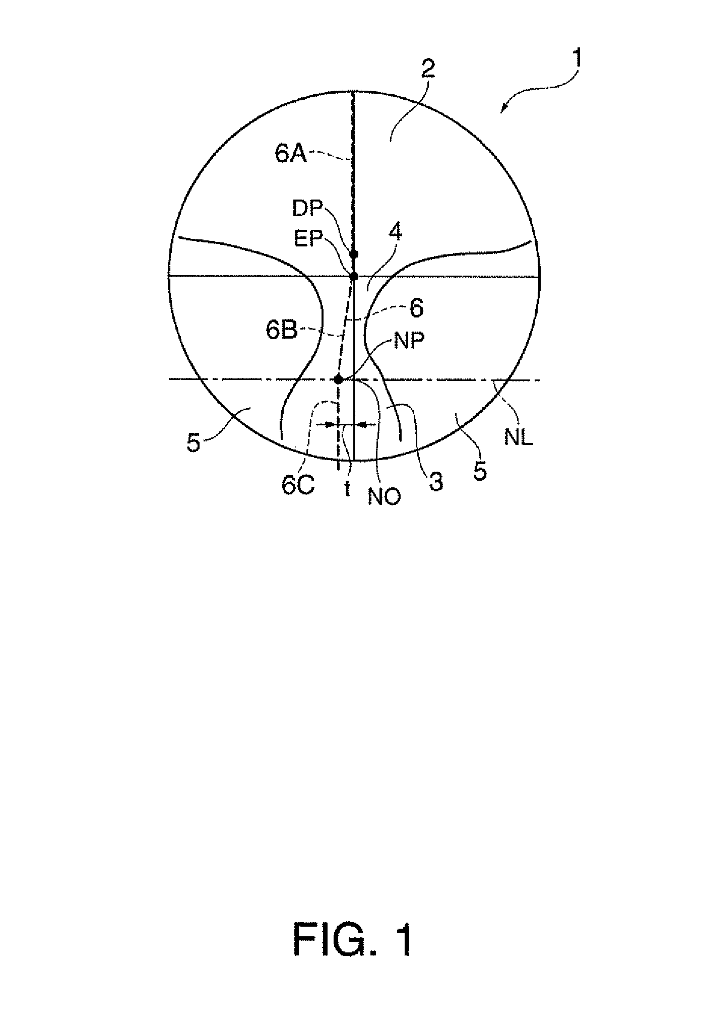
[0057]FIG. 1 is a schematic plan view of a spectacle lens according to the first embodiment.

[0058]In FIG. 1, a spectacle lens 1 is a progressive-power spectacle lens for near and far vision including a far region 2 provided in an upper portion of the spectacle lens 1 and corresponding to far vision, a near region 3 provided in a lower portion of the spectacle lens 1 and corresponding to near vision, an intermediate region 4 provided in an intermediate position of the spectacle lens 1 and having power continuously changing from that in the far region 2 to that in the near region 3, and intermediate side regions 5 provided on both sides of the intermediate region 4. The spectacle lens 1 shown in FIG. 1 is a spectacle lens for the right eye.

[0059]The far region 2, the near region 3, and the intermediate region 4 are formed on the inner surface (eyeball side) or the outer surface (opposite side to eyeball side) of the spectacle lens 1.

[0060]A princi...


PUM


Abstract

A spectacle lens includes: a near region corresponding to near vision, wherein a spherical equivalent power at a point located on a principal line of fixation in the near region is larger than the spherical equivalent power in a region away from the point toward the nose, in a horizontal direction with reference to a spectacle wearer but smaller than the spherical equivalent power in a region away from the point toward the ear in the horizontal direction.

Description

BACKGROUND[0001]1. Technical Field[0002]The present invention relates to a spectacle lens having a near region and a method for designing the spectacle lens.[0003]2. Related Art[0004]An example of a single-vision spectacle lens is a spectacle lens dedicated to near vision and having a near region provided substantially all over the lens, and a progressive-power spectacle lens has a near region provided in a lower portion of the lens. A progressive-power spectacle lens called a lens for near and far vision has a far region disposed above the near region and corresponding to far vision, an intermediate region which is disposed between the far and near regions and where the power continuously changes, and intermediate side regions provided on both sides of the intermediate region. A principal line of fixation (principal meridian) is formed along substantially central portions of the far, intermediate, and near regions.[0005]The principal line of fixation is an on-lens imaginary line wh...

Claims


Application Information

Patent Timeline
IPC IPC(8): G02C7/06
CPCG02C7/061G02C7/027G02C7/065
Inventor SUZUKI, YOHEI
Owner HOYA LENS MFG PHILIPPINES
Why Eureka
Try Eureka