
Electromagnetic regulator

a technology of actuating device and actuating plate, which is applied in the direction of valve details, basic electric elements, electrical apparatus, etc., can solve the problems of unwanted abrasion of material or even inability to operate the plunger unit, and reduce the service life of the plunger unit, so as to reduce friction and stress on the material, prevent unwanted transverse movement of the ball, and reliable rotation

Inactive Publication Date: 2011-09-01
ETO MAGNETIC GMBH
View PDF11 Cites 7 Cited by
  • Summary
  • Abstract
  • Description
  • Claims
  • Application Information

AI Technical Summary

Benefits of technology

[0006]The object is achieved by an electromagnetic actuating device having a plunger unit provided with a cage-like holding portion, into which a running or bearing ball is inserted rotatably in such a way that it can perform a rotary movement in the holding portion in reaction to the frictional or transverse force described above on the ball and in this way significantly reduces any possible friction-related abrasion of the material.
[0007]Here, the holding portion is preferably formed in such a way at the end of the plunger unit that, being formed integrally, that is to say from the material of the plunger unit and without an additional component, it acts in such a way that, on the one hand, an interior space (as a receiving chamber for the ball) is delimited or closed off in an effective manner, thus preventing the ball from falling out, while at the same time, however, allowing it to emerge by a predetermined amount from the cage-like holding portion in order to perform its running and bearing action and, on the other hand, that the prerequisites for reliable and free rolling (rolling movement) in a way which absorbs frictional forces in the manner described are provided within the receiving chamber.
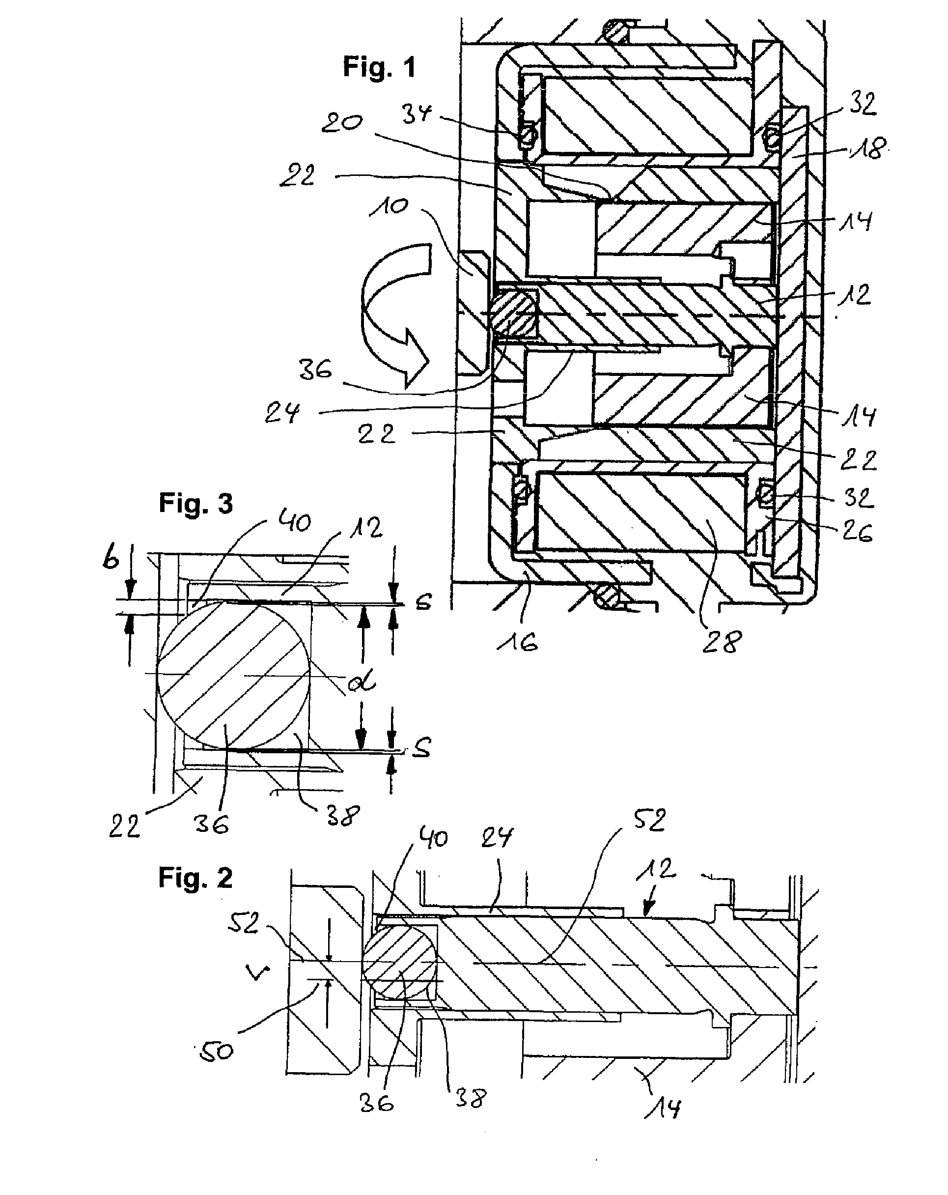
[0008]For this purpose, it is advantageous to configure an edge portion at the end of the receiving chamber to form a locking portion by appropriate inward flanging or folding (i.e. flanging or folding radially toward the center line), the corresponding wall portion in this embodiment of the invention being produced, with the running or bearing ball inserted, through the appropriate use of a tool for deformation. It is advantageous to set the (radial) extent of flanging, i.e. the reduction in the clear width in the transverse direction (and hence perpendicularly to the linear actuating movement of the plunger unit) to about 0.5% to 5%, relative to the diameter of the ball.
[0009]As an alternative and as a further preferred embodiment of the invention, provision is made (once again in an integral embodiment at the engagement end of the plunger unit) to form the end wall of the receiving chamber with an undercut which, once again, delimits a clear width of the receiving chamber (by running radially all the way round or around a section or sections) and in this way prevents the ball from falling out accidentally, thus producing the snap-fitting and / or locking effect according to the invention.
[0010]In this way, not only is it possible, reliably and advantageously in the manner described, to construct a receptacle for a running or bearing ball for force transmission to the actuating partner in a manner which reduces friction and stress on the material, but a procedure of this kind is simple in terms of assembly, not least because the running or bearing ball can be inserted into the holding cage simply by snapping or clipping it in.
[0011]It is within the scope of preferred developments of the invention to configure the inside width of the holding portion, i.e. a radial width of the receiving chamber for the running or bearing ball, with an oversize or clearance relative to the ball diameter in such a way that, on the one hand, reliable rotation, without jamming, is made possible in the desired manner and that, on the other hand, unwanted transverse movements of the ball are prevented. According to a development, appropriate configuration of the depth of the receiving chamber also ensures that the ball projects axially from the holding portion by 10% to 30%, once again relative to a ball outside diameter, for reliable actuating force transmission to the actuating partner.

Problems solved by technology

In devices existing in practice, this leads, for instance, to the end face of a valve slide unit which is interacting in an axially offset manner with the plunger unit exerting a radial force on the plunger unit during the movement of said valve slide unit, with the result that there is friction at the transitional surface or surface where the force is introduced, this friction causing unwanted abrasion of the material or even inability of the plunger unit to operate.
Nevertheless, it has been found in practice that it is precisely the difficult-to-avoid axial offset described above between the actuating partner and the plunger unit which leads to a considerable reduction in service life.

Method used


Image

  • Electromagnetic regulator
  • Electromagnetic regulator

Examples


Embodiment Construction

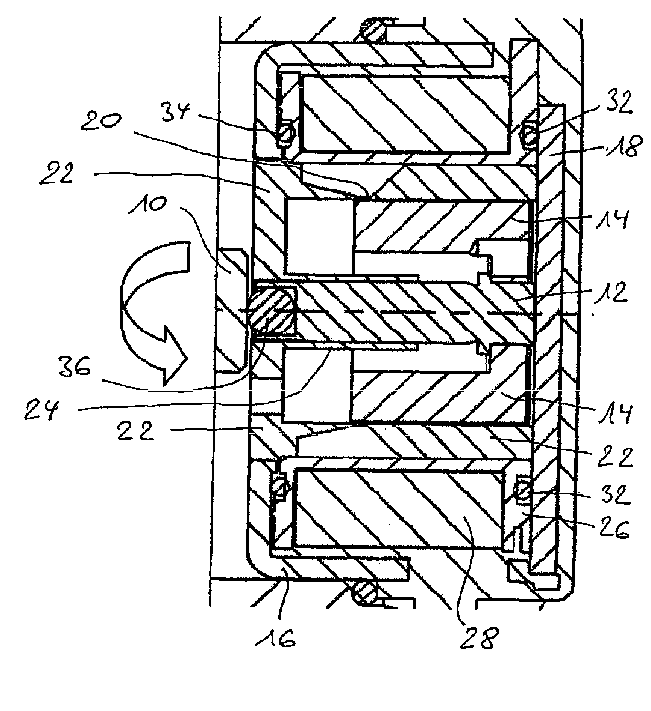
[0017]FIG. 1 shows, in a sectioned side view, the basic structure and the peripheral elements of the electromagnetic actuating device according to a first preferred embodiment, mounted for camshaft adjustment by means of a pressure force on a valve slide 10 (shown purely schematically and in section) of a switching valve unit (not shown) for camshaft adjustment on an internal combustion engine.

[0018]The linear thrust (to the left in the axial direction in the plane of the drawing in FIG. 1) on the valve slide unit 10 is exerted by a plunger unit 12, which is part of an armature unit of the electromagnetic actuating device shown and, together with a cup-shaped armature portion 14, forms the armature unit, which is guided in such a way that it can be moved within a two-part housing comprising a housing shell 16 and a housing base 18. More precisely, said armature unit 12, 14 is surrounded, for the purpose of forming a magnetic circuit, by a yoke core unit 22, which, in the present ill...


PUM


Abstract

An electromagnetic regulator having an armature unit with a plunger unit (12) carrying out a linear movement when energized by a current flowing in a stationary coil unit (26, 38), wherein the plunger unit is designed to cooperate at the end thereof with a regulator partner (10). The plunger unit has a slide or ball bearing (36) at the end thereof which is fixed in a cage-like housing (38, 40) on the plunger unit such as to be able to rotate in reaction to a frictional force at right angles to the direction of the linear regulation movement.

Description

BACKGROUND OF THE INVENTION[0001]The present invention relates to an electromagnetic actuating device. A device of this kind is well known from the prior art and is often used to actuate a (switching) valve and, in devices of the type in question, the electromagnetically driven armature unit interacts as an actuating partner with a valve slide or similar constructional unit of a switching valve of this kind in order to exert an actuating force by means of the linear actuating movement.[0002]One specific application which may be assumed to be known for devices of the type in question is adjustment of the camshaft of an internal combustion engine. Here, the actuating device of the type in question, as a pressure valve, is situated in an axial position relative to the engine camshaft. The vertically mounted actuating device makes contact by means of a front end surface of the plunger unit with the valve that effects camshaft adjustment.[0003]Manufacturing tolerances, thermally induced ...

Claims


Application Information

Patent Timeline
Patent Type & Authority Applications(United States)
IPC IPC(8): F16K31/02
CPCF16K31/06H01F7/1607H01F2007/086H01F2007/085H01F2007/083
Inventor BENDER, STEFAN
Owner ETO MAGNETIC GMBH
Learn More