
Weight measurement device

a weight measurement and weight technology, applied in the direction of measurement devices, weighing apparatus details, instruments, etc., can solve the problem of enlargement of the entire thickness of the weight measurement devi

Active Publication Date: 2011-09-01
TANITA CORP
View PDF17 Cites 8 Cited by
  • Summary
  • Abstract
  • Description
  • Claims
  • Application Information

AI Technical Summary

Benefits of technology

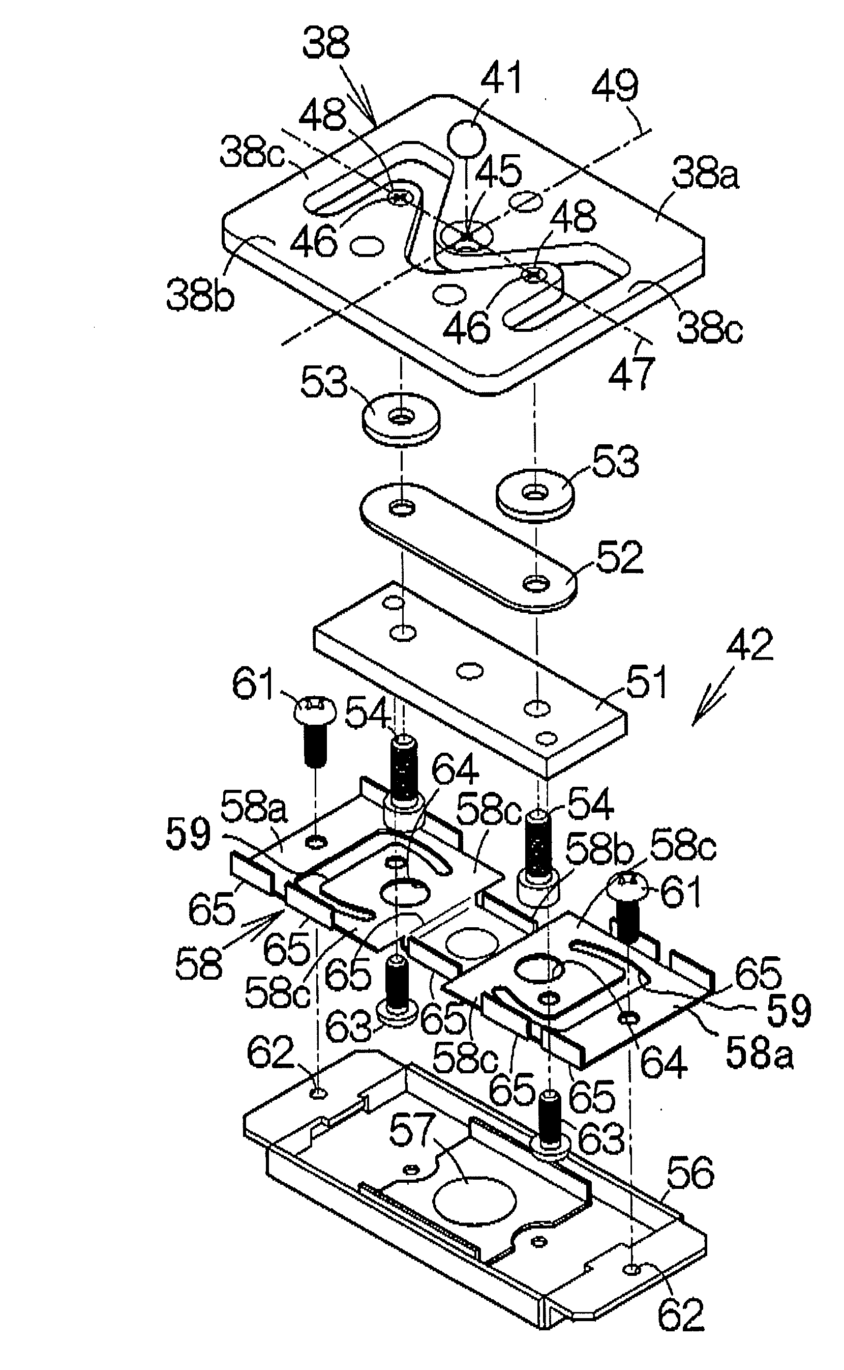
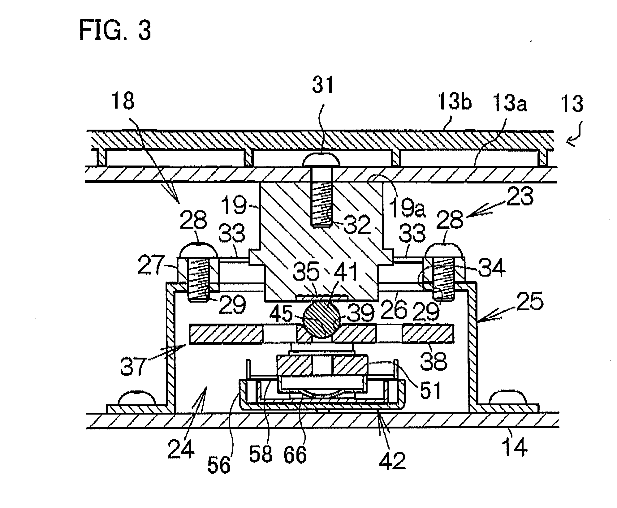
[0008]According to the present invention, there is provided a weight measurement device including: a housing including a base, a platform located above the base and on which a subject is placed or stands, and a chamber defined by the base and the platform; at least one load cell contained in the chamber and supported by the base; a load transmission member located between the platform and the load cell; a bracket fixed to the base; and an elastic deformation part located around the load transmission member and connected to the bracket and to the load transmission member, the elastic deformation part having an elasticity that is greater than that of the load transmission member, in which the elastic deformation part allows the load transmission member to change in position with respect to the bracket when force is transmitted from the platform via the load transmission member to the load cell.
[0009]In the weight measurement device, when a weight is applied to the platform, the weight is transmitted to the load transmission member. The load transmission member having less elasticity transmits the entire load exerted on the load transmission member 19 to the load cell with negligible loss of the load. As a result, the load cell can generate an electric signal that is accurately responsive to the weight exerted thereon. By virtue of the elastic deformation part having greater elasticity located around the load transmission member, the position (height and orientation (angle)) of the load transmission member is changeable due to deformation of the platform. Since the position of the load transmission member is not bound rigidly by the elastic deformation part having greater elasticity, the entire load exerted on the load transmission member is transmitted to the load cell with negligible loss of the load. The elastic deformation part is located around the load transmission member, and the elastic deformation part and any other large-deformation element are not interposed between the platform and the load cell. Therefore, the space between the platform and the base can be minimized, so that the weight measurement device is made thinner.
[0011]By virtue of the flexible plate and the point-support for the dome on the base, the load acceptor is changeable in position (height and orientation (angle)) with respect to the base. Consequently, notwithstanding deformation of the base, the fulcrum point on the flexure element is maintained in the same orientation with respect to the direction of gravitational force. Therefore, the deformation of the deformable region of the flexure element reflects accurately the load transmitted from the load transmission member to the force point on the flexure element.

Problems solved by technology

This results in enlargement of the entire thickness of the weight measurement device, such as a weighing scale.

Method used


Image

  • Weight measurement device
  • Weight measurement device
  • Weight measurement device

Examples


Embodiment Construction

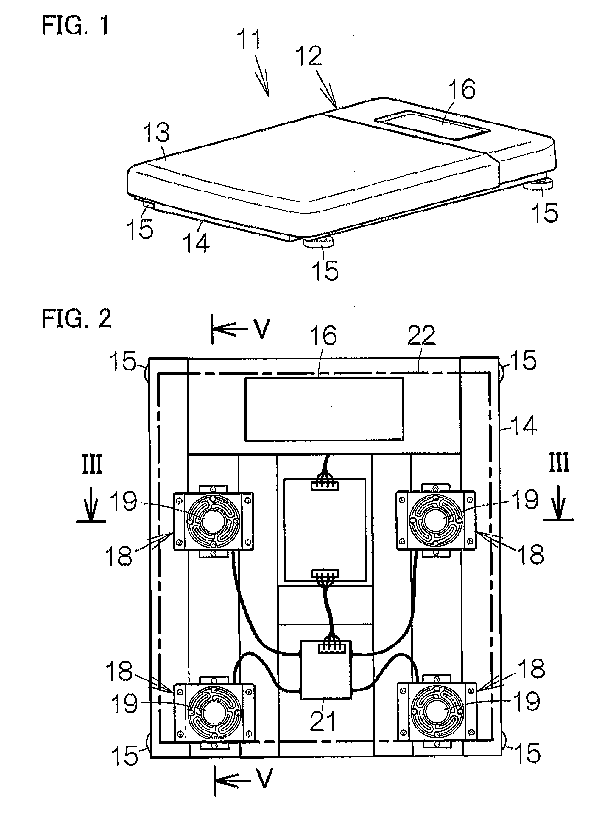
[0021]FIG. 1 shows a weight measurement device, i.e., a weighing scale 11 according to an embodiment of the present invention. The weighing scale 11 includes a housing 12 including a platform 13 that includes an upper surface that may be planer and horizontal. A user of the weighing scale 11 stands on the platform 13.

[0022]The housing 12 includes a base 14. The base 14 is made of a rigid material, for example, stainless steel. The base 14 is formed into a substantially rectangular shape in plane view as shown in FIG. 2. At the four corners of the rectangular shape, legs 15 are fixed. The length of each leg 15 with respect to the base 14 may be adjustable, so that the orientation of the platform 13 can be adjusted with respect to the horizontal and the upper planar surface of the platform 13 can be deployed horizontally. Such adjustment of the length of each leg 15 is achieved by, for example, providing each leg with a screw having a vertically oriented axis.

[0023]The platform 13 cov...


PUM


Abstract

A weight measurement device has a housing that includes a base, a platform located above the base and on which a subject is placed or stands, and a chamber defined by the base and the platform. At least one load cell is contained in the chamber and is supported by the base. A load transmission member is located between the platform and the load cell. A bracket is fixed to the base. An elastic deformation part is located around the load transmission member and connected to the bracket and to the load transmission member. The elastic deformation part has an elasticity that is greater than that of the load transmission member, and allows the load transmission member to change in position with respect to the bracket when force is transmitted from the platform via the load transmission member to the load cell.

Description

BACKGROUND OF THE INVENTION[0001]1. Field of the Invention[0002]The present invention relates to weight measurement devices, for example, weighing scales.[0003]2. Related Art[0004]In a conventional weighing scale, there may be a chamber defined by a base and a platform on which a subject stands, and one or more load cells are contained in the chamber as disclosed in JP 2003-307454-A and JP 2004-156937-A. The load cell generates an electric signal due to the weight exerted on the platform. On the basis of the electric signal, the amount of weight on the platform is calculated.[0005]The load cell incorporates a flexure element having a fulcrum point supported with respect to the base and a force point (application point of the force) coupled to the platform. When a load is applied to the force point from the platform, the part of the flexure element between the force point and the fulcrum point deforms, and the degree of deformation is measured with a suitable element, for example, a ...

Claims


Application Information

Patent Timeline
Patent Type & Authority Applications(United States)
IPC IPC(8): G01G3/12
CPCG01G21/244G01G21/23G01G21/184
Inventor HONDA, AKIHISAHATAKEYAMA, MINORU
Owner TANITA CORP
Learn More