Current driver for LED

a current driver and led technology, applied in the direction of instruments, light sources, electroluminescent light sources, etc., can solve the problems of limited efficiency of such drivers and few drivers available to operate at ac line voltag

Inactive Publication Date: 2011-08-25
ALBRECHT JOHN C
View PDF1 Cites 2 Cited by
  • Summary
  • Abstract
  • Description
  • Claims
  • Application Information

AI Technical Summary

Benefits of technology

[0007]The input energy required to drive an LED load is less than the energy required to drive the same LED load with DC.
[0008]A driver comprises an input capacitor, and a full wave rect

Problems solved by technology

The efficiencies of such drivers are limited by power losses in their respective circuits employed to control their output currents or voltages.
There are few drivers available to operate at AC line voltages.
Unfortunately, commercially available drivers require added inp

Method used


Image

  • Current driver for LED
  • Current driver for LED
  • Current driver for LED

Examples


example b

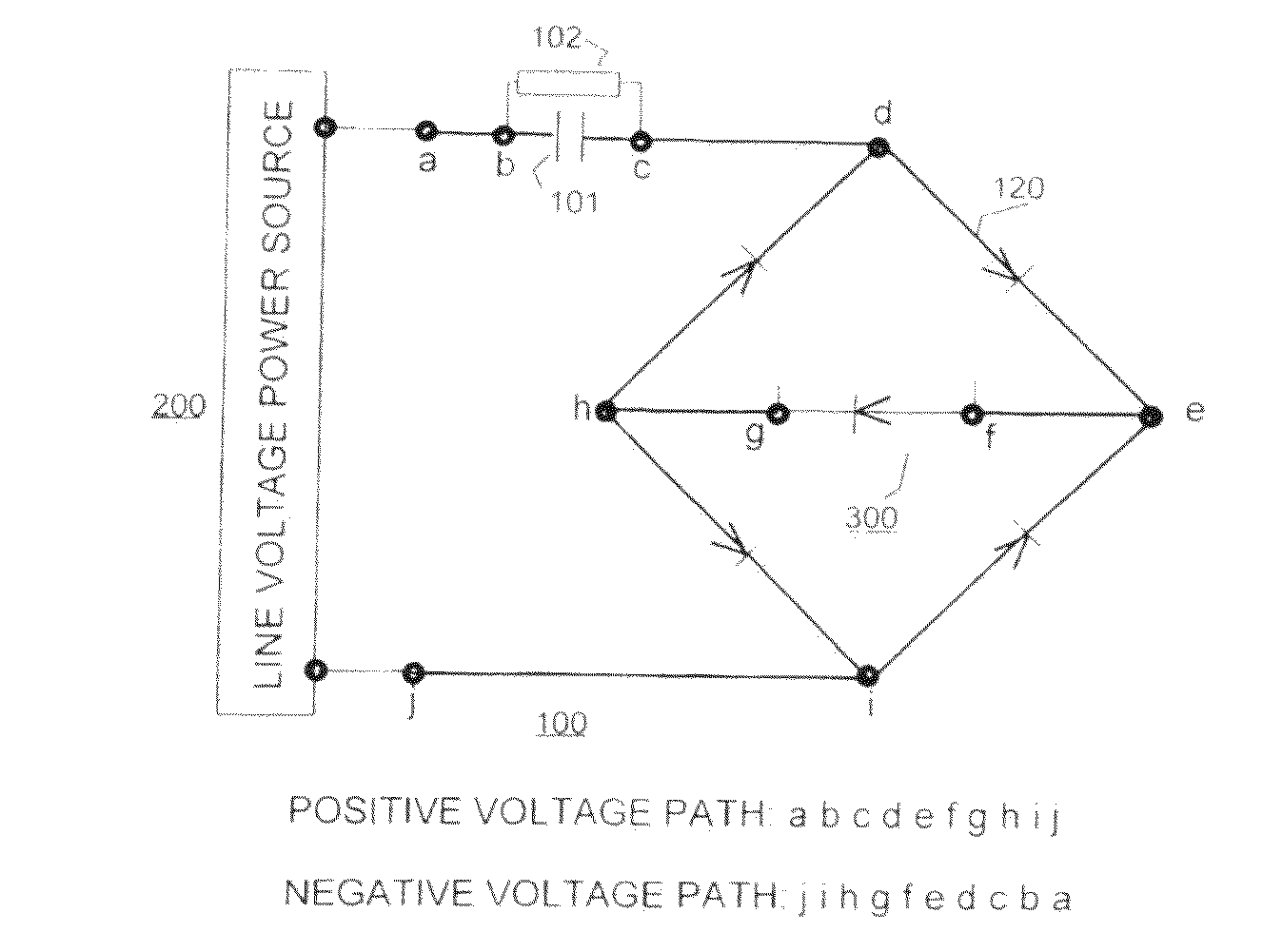
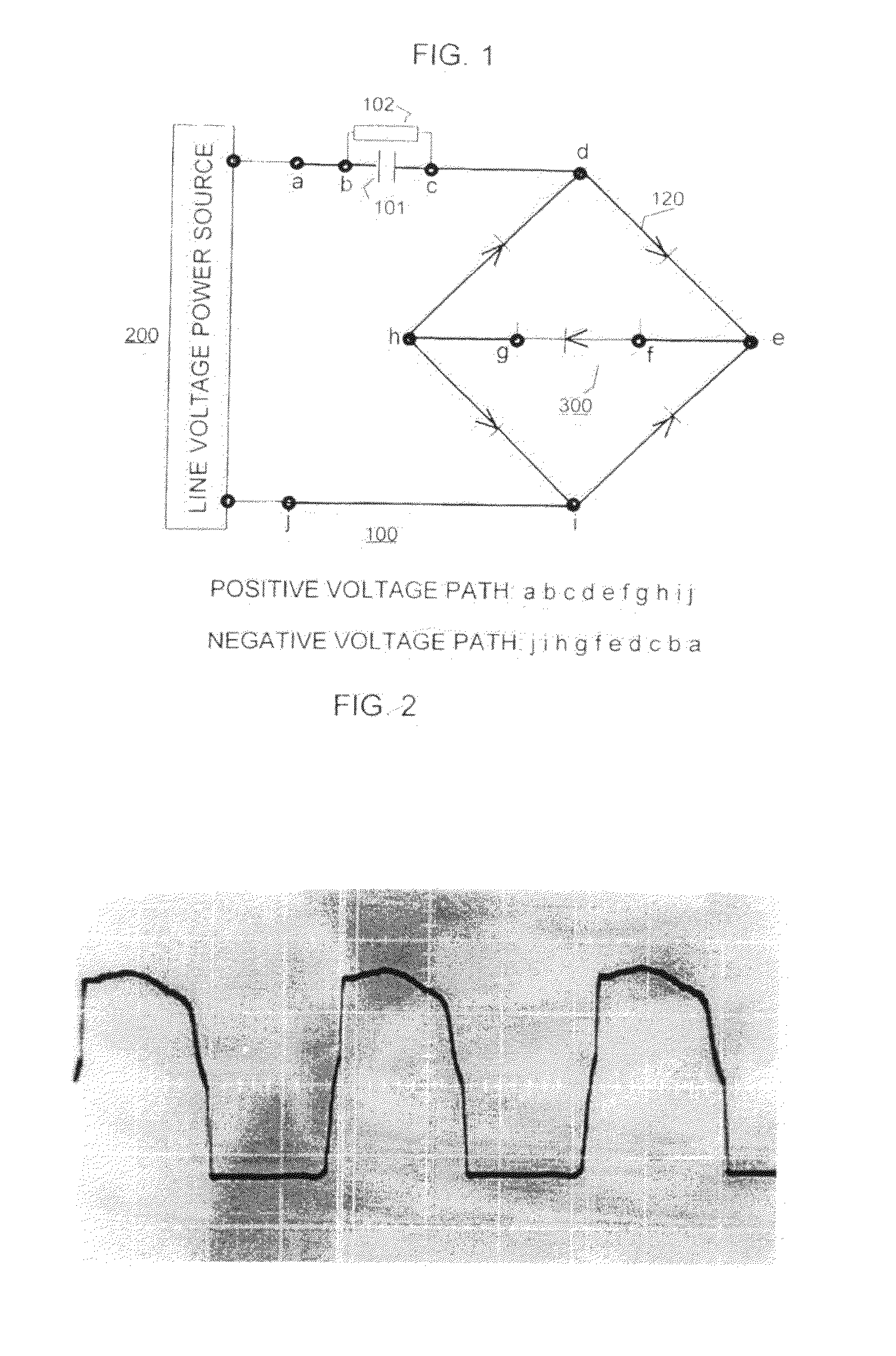
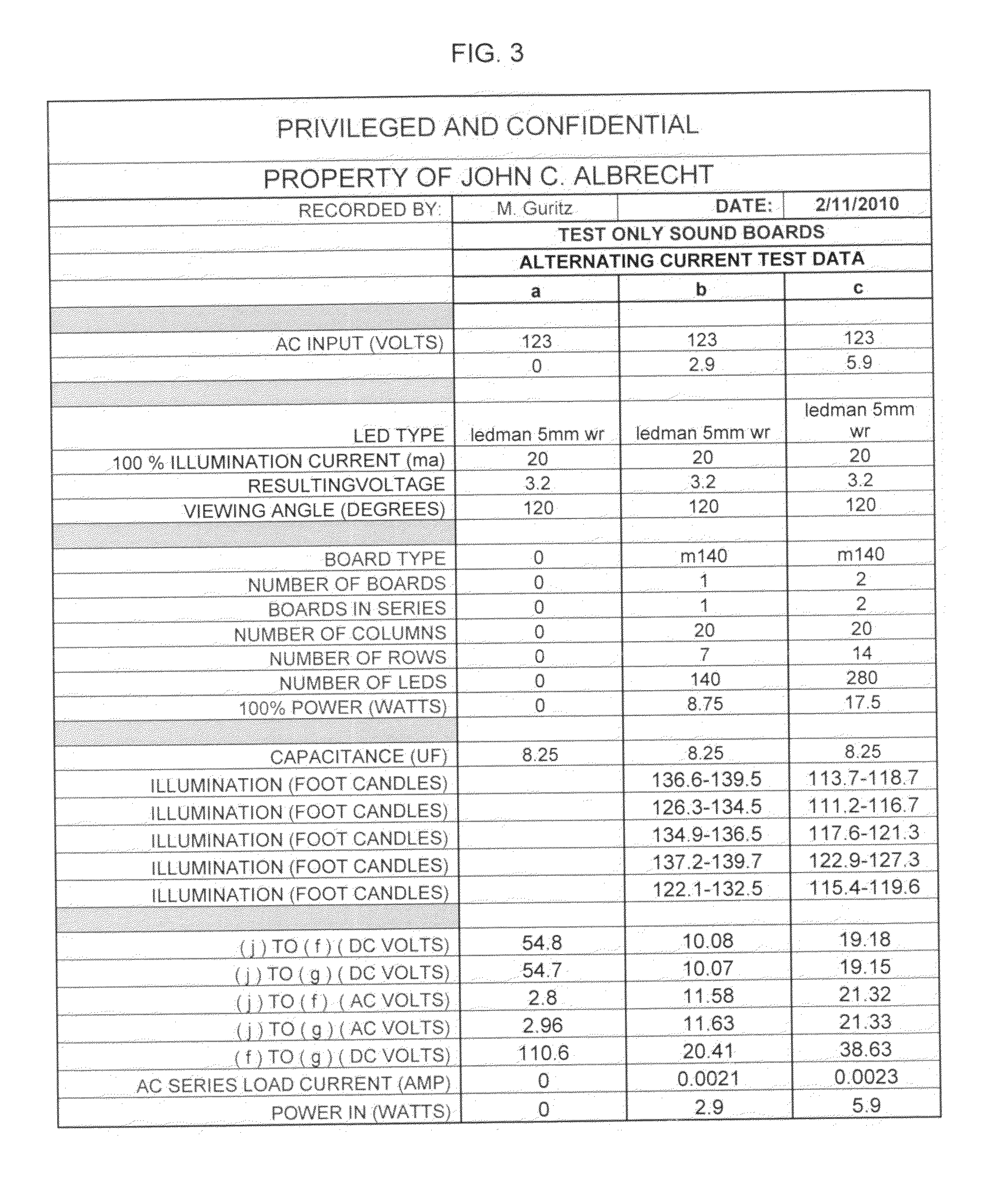
[0034 of FIG. 3, powers 140 5 mm LEDs arranged in twenty parallel columns, each column is comprised of 7 series connected LEDs. The AC power drawn is: 0.0021×60×23.21=2.92 watts.

[0035]If the assembly 300, is driven by DC and produces the same reported levels of illumination in foot candles, the DC power drawn is 6 watts.

[0036]In example c of FIG. 3, the assembly of 280 LEDs is comprised of 20 columns and 14 rows. The AC power drawn by above AC driver consumes 2.7 watts, and the DC driver draws 5 watts.

[0037]The driver circuit of FIG. 3 provisioned with an 8.25 micro farad capacitor produced the target ranges of reported light levels. Different target levels of illumination of an LED assembly can be met by matching the capacitance of capacitor 101 to the structure and target illumination levels of LED assembly 300.

[0038]The illumination levels reported in FIG. 3 were measured by use of a light meter receiving light via a tube positioned on an LED to assure uniformity in determining l...


PUM


Abstract

A current driver for powering an LED assembly comprises an input capacitor and a full wave rectifier. The LED assembly is connected to the rectifier output terminals. A driven LED assembly may be formed of series and parallel strings of individual LEDs. AC Line frequencies, e.g., 50 cycles, 60 cycles, non-line AC frequencies; and ranges of source voltages, e.g., 120 to 220 volts are accommodated by the driver. The driver provides essentially equal energy current pulses to the LED load, coincident with the time and the duration of the positive excursions of the input power. Energy is delivered to the LED load in a 50% duty cycle. Transfer of energy from an AC input power source to an LED assembly is independent of the output parameters of that source.

Description

BACKGROUND OF THE INVENTION[0001]InGaN blue Light Emitting Diodes (LEDs) opened the way for manufacture of “white” light LED assemblies comprising a dice of InGaN and a light excited phosphor. White light LEDs are available in the forms of 3 mm, 5 mm and 10 mm bottles and Surface Mounted Devices (SMDs). High Power white LEDs, rated at 1 watt and 5 watts, are widely used. The foot print of the light of individual LEDs is determined principally by the shape and the material of the individual LED enclosures. All of the above products can be economically powered by the circuitry disclosed herein. Although manufacturers of white light LEDs publish “detailed specifications” of their products, specifications which are provided to a customer with a shipment, appear to differ from the published “detailed specifications”. Extensive testing of 5 mm LED products appears to indicate similar variations.[0002]The forward current path through an (LED) is essentially free of resistance, and the seri...

Claims


Application Information

Patent Timeline
IPC IPC(8): H05B37/02
CPCH05B33/0806H05B45/30H05B45/32
Inventor ALBRECHT, JOHN C.
Owner ALBRECHT JOHN C
Why Eureka
Try Eureka