
Conveying apparatus, recording apparatus, conveying method, and recording method

a technology of conveying apparatus and recording apparatus, which is applied in the directions of transportation and packaging, pile separation, packaging, etc., can solve the problems of poor recording quality

Active Publication Date: 2011-08-25
SEIKO EPSON CORP
View PDF5 Cites 2 Cited by
  • Summary
  • Abstract
  • Description
  • Claims
  • Application Information

AI Technical Summary

Benefits of technology

[0008]The present invention was devised in view of such problems described above, and an object thereof is to provide a conveying apparatus, a recording apparatus, a conveying method, and a recording method in which the bag can be kept flat.
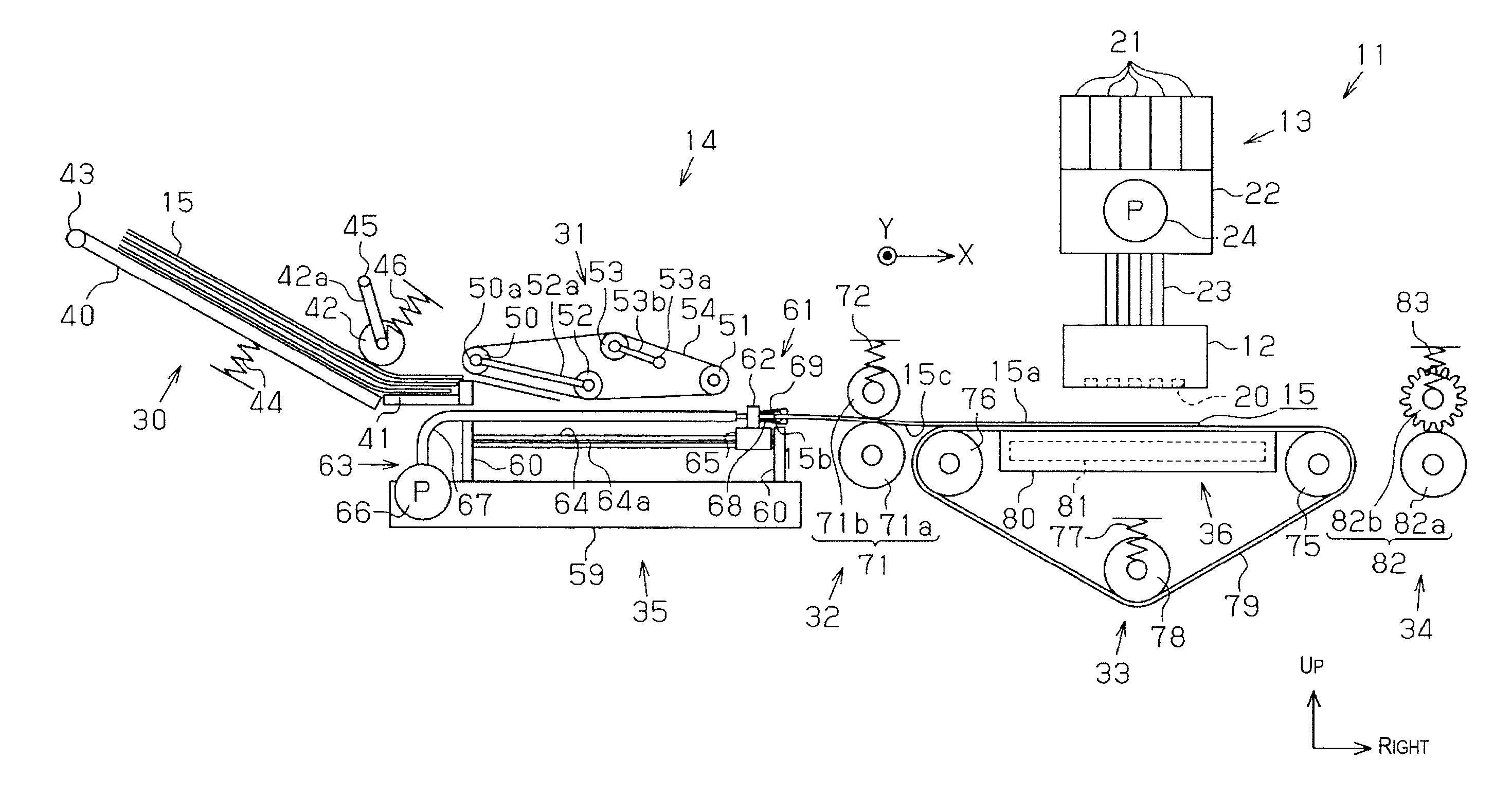
[0010]According to the aforedescribed aspect, negative pressure can be created inside the bag by suctioning the interior of the bag by the suction mechanism, and the bag can be kept flat.
[0020]According to the aforedescribed aspect, the bag can be kept flat by the suction mechanism. Thereby, when the recording unit performs the recording process on the external surface of the bag, it is possible to prevent poor recording quality caused by unevenness in the external surface serving as the recording surface of the bag.
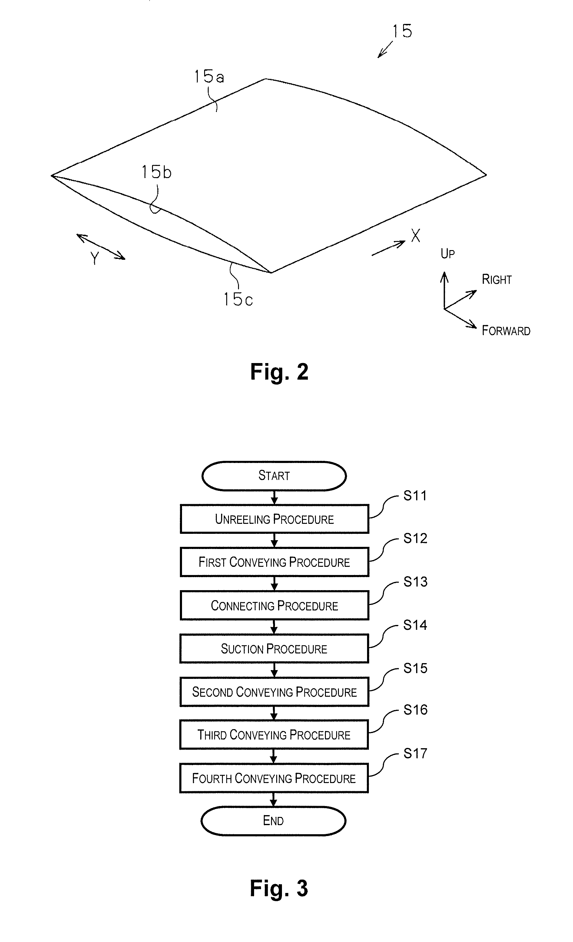
[0024]According to the aforedescribed aspect, the bag can be kept flat by creating negative pressure in the interior of the bag during the suction procedure.

Problems solved by technology

There has been a problem with poor recording quality due to printing on a recording surface in which the remaining air has caused unevenness.

Method used


Image

  • Conveying apparatus, recording apparatus, conveying method, and recording method
  • Conveying apparatus, recording apparatus, conveying method, and recording method
  • Conveying apparatus, recording apparatus, conveying method, and recording method

Examples


first embodiment

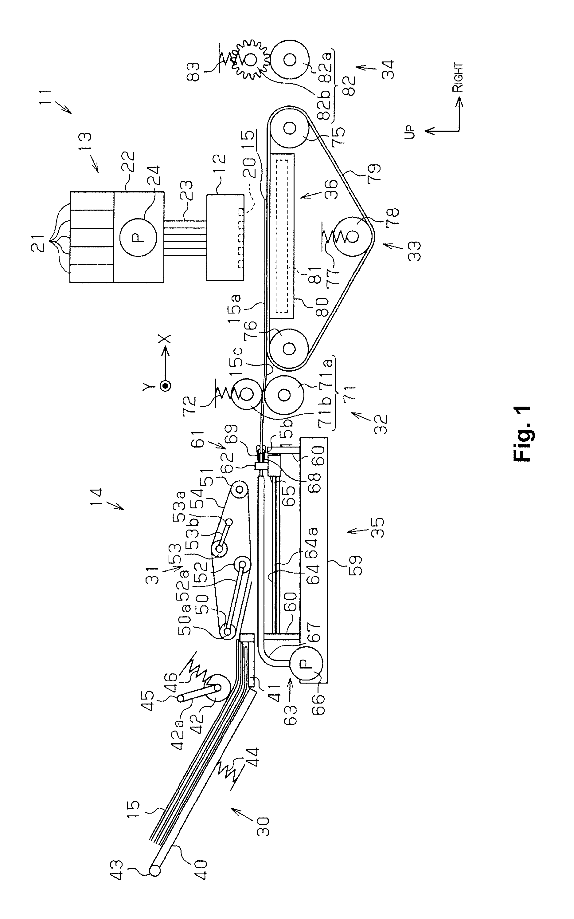
[0040]The first embodiment is described hereinbelow with reference to FIGS. 1 through 9, wherein the present invention is specified as an inkjet recording apparatus (hereinbelow referred to simply as “printer”), which is one type of a recording apparatus. In the description hereinbelow, the terms “forward-backward direction,”“left-right direction,” and “up-down direction,” refer respectively to the forward-backward direction, left-right direction, and up-down direction indicated by the arrows in the drawings.

[0041]A printer 11 comprises a recording head 12 as a recording unit, an ink supply mechanism 13 for supplying ink as a fluid to the recording head 12, and a conveying apparatus 14, as shown in FIG. 1. The recording head 12 performs a recording process on a bag 15 made of a resin film or the like.

[0042]The bag 15 is used in order to package foodstuffs or the like, for example, wherein three of the four edges of vertically stacked sheets are sealed, and an opening 15b is formed i...

second embodiment

[0089]The following is a description of the second embodiment, made with reference to FIGS. 10 through 12, wherein the configurations of the unreeling portion 30 and the first conveying portion 31 have been changed from those in the printer 11 of the first embodiment. The other portions are identical to the first embodiment, and drawings and descriptions thereof are therefore omitted.

[0090]An unreeling portion 30A of the present embodiment comprises supply rollers 85 to the right of an unreeling guide 41A, as shown in FIG. 10. The supply rollers 85 are configured from a drive roller 85a for supporting the bag 15 from below, and a driven roller 85b constituting a pair with the drive roller 85a. The driven roller 85b is urged by an urging member 86 in a direction toward the drive roller 85a. The urging direction of the driven roller 85b in relation to the drive roller 85a is adjusted in order for the supply rollers 85 to supply the bag 15 to the conveying route formation member 64 pos...


PUM

PropertyMeasurementUnit
Flexibilityaaaaaaaaaa

Abstract

A conveying apparatus includes a suction mechanism that suctions an interior of a bag, and a connecting mechanism that connects an opening of the bag and the suction mechanism.

Description

CROSS-REFERENCE TO RELATED APPLICATIONS[0001]This application claims priority to Japanese Patent Application No. 2010-039142 filed on Feb. 24, 2010. The entire disclosure of Japanese Patent Application No. 2010-039142 is hereby incorporated herein by reference.BACKGROUND[0002]1. Technical Field[0003]The present invention relates to a conveying apparatus, a recording apparatus, a conveying method, and a recording method.[0004]2. Related Art[0005]Conventionally, inkjet printers which spray ink or another fluid onto a medium are widely known as recording apparatuses. Such printers have included those applied to printing manufacturing dates or other information, for example, on the external surfaces of bags for packaging foodstuffs and the like (Japanese Laid-Open Patent Application No. 2000-264317, for example).[0006]When printing as a recording process is performed on a bag in this manner, the external surface used as the recording surface must be held in a flat state in the recording...

Claims


Application Information

Patent Timeline
IPC IPC(8): B65H5/06B65H5/00
CPCB41J3/407B41J11/007B41J11/0085B65B61/025B65B61/26B41J29/00B65H2301/5124B65H2406/30B65H2601/211B65H2701/191B65H5/224
Inventor MATSUHASHI, KUNIHIKO
Owner SEIKO EPSON CORP
Learn More