
Day and time chronometer movement

a chronometer and movement technology, applied in the field of chronometers, can solve problems such as difficult to solve, difficult to set the day of the week, and the approach does not work well when adopted, and achieve the effect of accurately setting the day and tim

Inactive Publication Date: 2011-08-18
DAYTIME LLC
View PDF16 Cites 3 Cited by
  • Summary
  • Abstract
  • Description
  • Claims
  • Application Information

AI Technical Summary

Benefits of technology

[0012]This patent discloses and claims a useful, novel, and unobvious invention for a clock with a continuously moving day hand in the chronometer field.
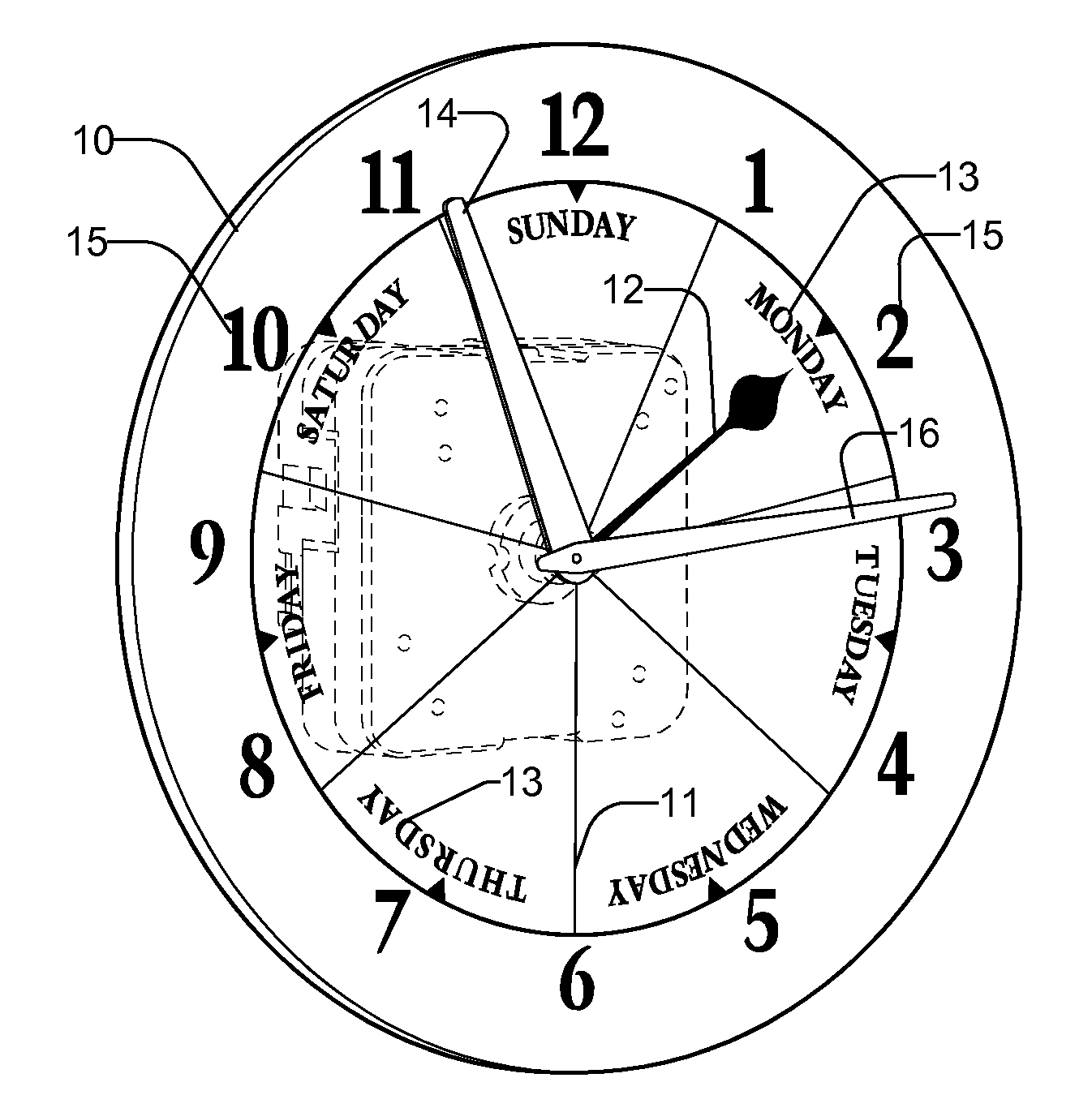
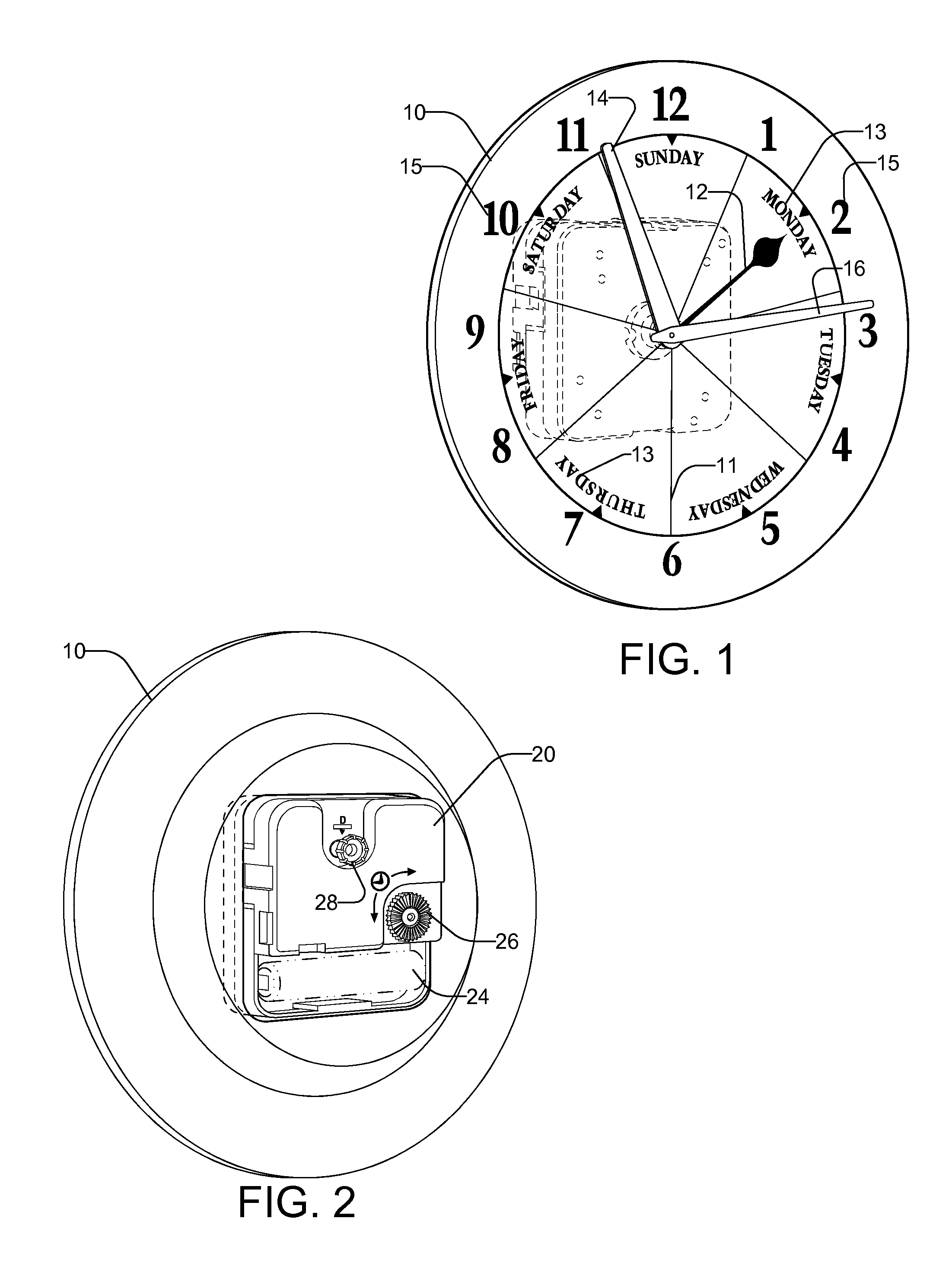
[0013]A day clock has day, hour, and minute hands revolving continuously around a common center. It has a time adjustment knob and a day adjustment knob. When the day adjustment knob is pulled out, a set of gears are disengaged, allowing the day hand to be adjusted with that knob without affecting the other hands. Then, when the set of gears are reengaged, the time adjustment knob can be utilized to set the time of day. In order to set the day and time accurately, the user may first set the time to midnight with the time adjustment knob, pull out the day adjustment knob, set the day to a clock face line between days with that knob, push that knob back in, and then set the time to the correct time with the time adjustment knob.

Problems solved by technology

However, it was discovered that multiple gears could be fixably mounted on the same shaft, and that gear trains so constructed were simpler to construct and often easier to design and took up less space.
One problem that has been difficult to solve is that of setting the day of the week.
But that approach does not work well when adopted to adjusting a day hand, because in order to adjust the day and time ahead by 3 days 2 hours and 15 minutes, one would need to rotate the minute hand 74¼ times (3*24+2+¼) around the clock face.

Method used


Image

  • Day and time chronometer movement
  • Day and time chronometer movement
  • Day and time chronometer movement

Examples


Embodiment Construction

[0021]A Day Clock is a clock that displays the day of the week, along with possibly the hour, minute, and second. In this invention, the Day, Hour, Minute, and Second hands are mounted on concentric shafts, so that these hands can rotate simultaneously and continuously around a common center. A Time Adjustment Knob and a Day Adjustment Knob are provided. Pulling out the Day Adjustment Knob disengages the gears driving the Day hand from the gears driving the other hands. The Day hand can then be adjusted independently of the other hands utilizing this knob. This knob is then pushed in, reengaging the gears, allowing the Day hand to move along with the other hands, and to be adjusted along with the other hands by the Time Adjustment Knob.

[0022]In the following disclosure, multiple gears are most often mounted on a common shaft on what will be termed herein as a “gear assembly”. A gear assembly will have one, two, or possibly more gears fixably attached to a common shaft, which may be ...


PUM


Abstract

A day clock has day, hour, and minute hands revolving continuously around a common center. It has a time adjustment knob and a day adjustment knob. When the day adjustment knob is pulled out, a set of gears are disengaged, allowing the day hand to be adjusted with that knob without affecting the other hands. Then, when the set of gears are reengaged, the time adjustment knob can be utilized to set the time of day. In order to set the day and time accurately, the user may first set the time to midnight with the time adjustment knob, pull out the day adjustment knob, set the day to a clock face line between days with that knob, push that knob back in, and then set the time to the correct time with the time adjustment knob.

Description

CROSS-REFERENCE TO RELATED APPLICATIONS[0001]This application is a continuation-in-part of co-pending U.S. patent application Ser. No. 10 / 789,388, filed Feb. 28, 2004, the entirety of which is incorporated by reference herein.BACKGROUND OF THE INVENTION[0002]1. Field of the Invention[0003]The present invention relates to chronometers and, more specifically, to a clock that displays a continuously moving day hand.[0004]2. The Prior Art[0005]Clocks and other types of chronometers have an ancient lineage. Some of the earlier clocks used peg and tooth gears in order to display hours and minutes somewhat accurately. More recently, many chronometers use gear trains of toothed gears to provide this feature.[0006]Basic gears work on the principle that when two circles are turning with their edges at the same speed, their relative rotational speeds are a function of the difference in their circumference, which are, in turn, dependent upon their respective radii or diameters, through use of t...

Claims


Application Information

Patent Timeline
Patent Type & Authority Applications(United States)
IPC IPC(8): G04B19/24
CPCG04B19/24G04F8/00G04C3/00
Inventor KALLESTAD, JOHN P.
Owner DAYTIME LLC
Learn More