
Electric cord reel

a technology of electric cords and reels, applied in the direction of electrical cables, electrical equipment, cable arrangements between relatively moving parts, etc., can solve the problems of deficiency in prior technology and tangled extension cords

Inactive Publication Date: 2011-08-18
HALL JOHN ERNEST
View PDF28 Cites 3 Cited by
  • Summary
  • Abstract
  • Description
  • Claims
  • Application Information

AI Technical Summary

Benefits of technology

"The invention is a cord reel that has several technical effects. First, it is stable and does not tip over when the cord is pulled from the reel. Second, it is easy to reel in and out the cord. Third, it can connect with any amount of cord being extended from the reel. Fourth, it can accommodate any available extension cord. Fifth, it helps guide the cord back onto the reel. Sixth, it allows the user access to either the male or female end of the cord. Seventh, it allows the user to move freely within the length of the extended cord. Eighth, it can accommodate a wide variety of lengths or weights of extension cords. Ninth, it is easy and economical to manufacture. Tenth, it can be hung up for storage or use in the hung position. Overall, the invention provides a versatile and convenient solution for managing cords and plugs."

Problems solved by technology

The extension cords tend to become tangled either during use or in the storage mode.
However there is a deficiency in the prior technology because the prior art does not include all the novel and helpful features contained within one embodiment presented herein including, the ability to use any extension cord, having a cord guide aperture, having a tip proof support structure and to allow easy access to either the male end of the extension cord or the female end of the extension cord.

Method used


Image

  • Electric cord reel
  • Electric cord reel
  • Electric cord reel

Examples


Embodiment Construction

[0035]Detailed descriptions of the preferred embodiment are provided herein. It is to be understood, however, that the present invention may be embodied in various forms. Therefore, specific details disclosed herein are not to be interpreted as limiting, but rather as a basis for the claims and as a representative basis for teaching one skilled in the art to employ the present invention in virtually any appropriately detailed system, structure or manner.

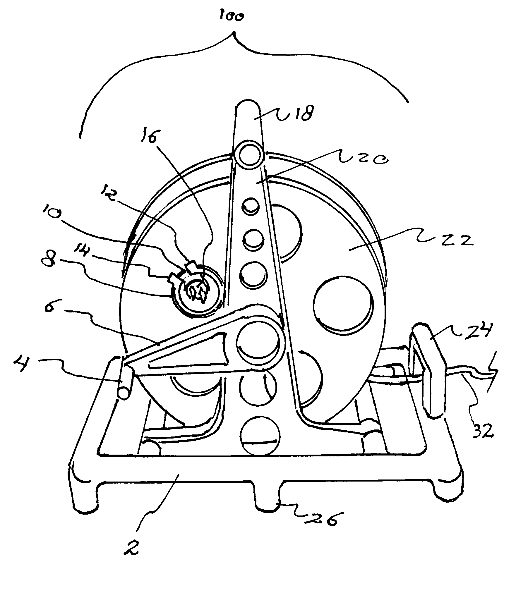
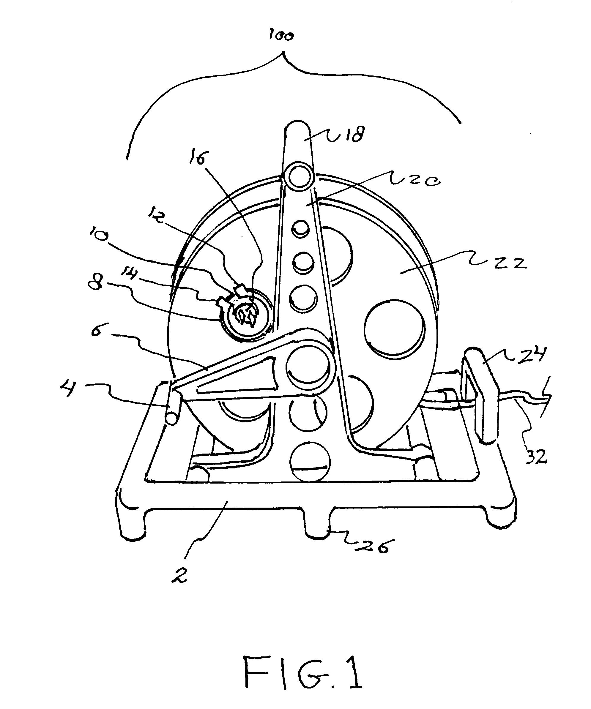
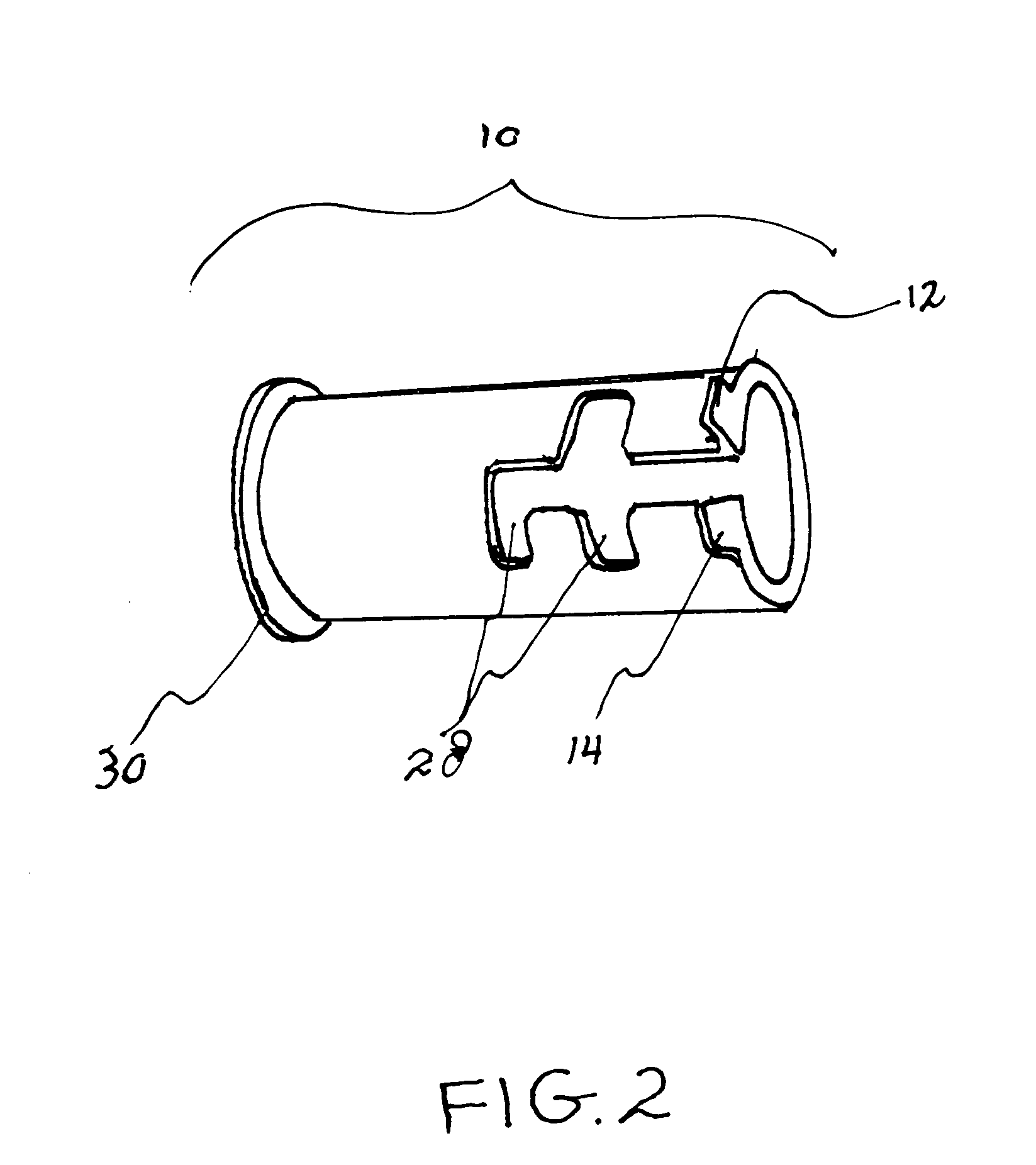
[0036]Referring now to FIG. 1 we see a perspective view of the cord reel assembly of the present invention 100. The assembly consists of a reel 22, a support structure 20 a hand crank 6 and handle 4. The reel 22 is rotatably supported by the support structure 20. The top cross piece 18 of the support structure side walls 22 also acts as a carry handle. An aperture 8 as well as aperture 9 shown in FIG. 4 holds a cord support tube 10. The support tube as shown in FIG. 2 shows that the tube 10 has a flange 30 on one end and a plurality ...


PUM


Abstract

Electric cord reel with a reel, a crank and handle, a reel support structure, a base structure, a guide aperture and a cord and plug retaining tube the reel is rotatably attached to the reel support structure The handle fixedly attached to the pivot point of the reel wall. The support structure is fixedly attached to the base structure. The guide aperture fixedly attached to the base structure so that it is in alignment with the spool portion of the reel. The cord and plug retaining tube is removably attached to left and right apertures in the walls of the reel. A standard extension cord portion and plug can be removably retained within the cord and plug retaining tube. A preferred embodiment includes the base structure having a plurality of downwardly facing legs that help keep the structure from sliding when a user pulls on the electric cord.

Description

CROSS REFERENCE TO RELATED APPLICATIONS[0001]Not ApplicableSTATEMENT REGARDING FEDERALLY SPONSORED RESEARCH OR DEVELOPMENT[0002]Not ApplicableDESCRIPTION OF ATTACHED APPENDIX[0003]Not ApplicableBACKGROUND OF THE INVENTION[0004]This invention relates generally to the field of cord organizing appliances and more specifically to an electric cord reel.Extension cords are often used when doing yard work involving electrically powered tools.The extension cords tend to become tangled either during use or in the storage mode.To solve this problem, the use of a reel to wind up the cord is advantageous. To this end, a number of inventors have proposed reel designs to help keep cords from becoming tangled. Patents that show this type of solution include the following patents presented in chronological order:[0005]U.S. Pat. No. 3,782,654[0006]U.S. Pat. No. 3,876,045[0007]U.S. Pat. No. 3,880,378[0008]U.S. Pat. No. 4,061,290[0009]U.S. Pat. No. 4,136,840[0010]U.S. Pat. No. 4,244,536[0011]U.S. Pat....

Claims


Application Information

Patent Timeline
Patent Type & Authority Applications(United States)
IPC IPC(8): H02G11/02B65H75/38
CPCH02G11/02B65H2701/34B65H75/40B65H75/28
Inventor HALL, JOHN
Owner HALL JOHN ERNEST
Learn More