
Stepping-free electric dehydration barrel

a technology of electric dehydration and electric motor, which is applied in the direction of spin-dryers, carpet cleaners, lighting and heating apparatus, etc., can solve the problems of inconvenient use of dehydration barrels and easy arousal of curiosity by children, and achieve the effect of easy and rapid dehydration

Inactive Publication Date: 2011-08-18
SHIH SHU CHEN
View PDF11 Cites 14 Cited by
  • Summary
  • Abstract
  • Description
  • Claims
  • Application Information

AI Technical Summary

Benefits of technology

[0007]A user only needs to put a mop into the dehydration basket and then exert a downward force to the dehydration basket through the mop that the elastic lifting unit can be descended to turn on the starting switch, so as to drive the dehydration basket spinning in a high speed to fling off water, thereby achieving an object of easily and rapidly dehydrating.
[0008]To prevent the dehydration basket from being touched accidentally by a mistake to spin in a high speed, the present invention is further provided with a safety switch which is electrically connected with the control unit, such that under a condition that the safety switch is not activated, even when the elastic lifting unit is descended to trigger the starting switch, the control unit will still not activate the motor, thereby preventing the dehydration basket from being touched by a mistake to spin in a high speed.
[0009]In comparison with the prior art, the present invention is at least provided with following advantages that:
[0010]1. A condition of forcing the user to stand by one foot can be avoided;
[0011]2. The provision of the safety switch can prevent the dehydration basket from being touched by a mistake to spin in a high speed; and
[0012]3. A lead wire assembly having a connector can facilitate replacing the rechargeable battery.

Problems solved by technology

An existing dehydration barrel, a dehydration basket of which is driven by a motor, still requires a user to step on a switch paddle to activate the dehydration basket for spinning, wherein as the user needs to step by one foot when using the dehydration barrel, a configuration of standing by one foot will be formed such that the dehydration barrel will be rather inconvenient in usage.
In addition, the provision of the paddle will easily arouse curiosity of children to play with.

Method used


Image

  • Stepping-free electric dehydration barrel
  • Stepping-free electric dehydration barrel
  • Stepping-free electric dehydration barrel

Examples


first embodiment

[0024]Referring to FIG. 1 and FIG. 2, it shows a local cutaway view and a top view of the present invention. As shown in the drawings, a stepping-free electric dehydration barrel comprises primarily a barrel unit 10, a dehydration unit 20, a motor 30, a control unit 40, a rechargeable battery 50 and a recharging connection port 60.

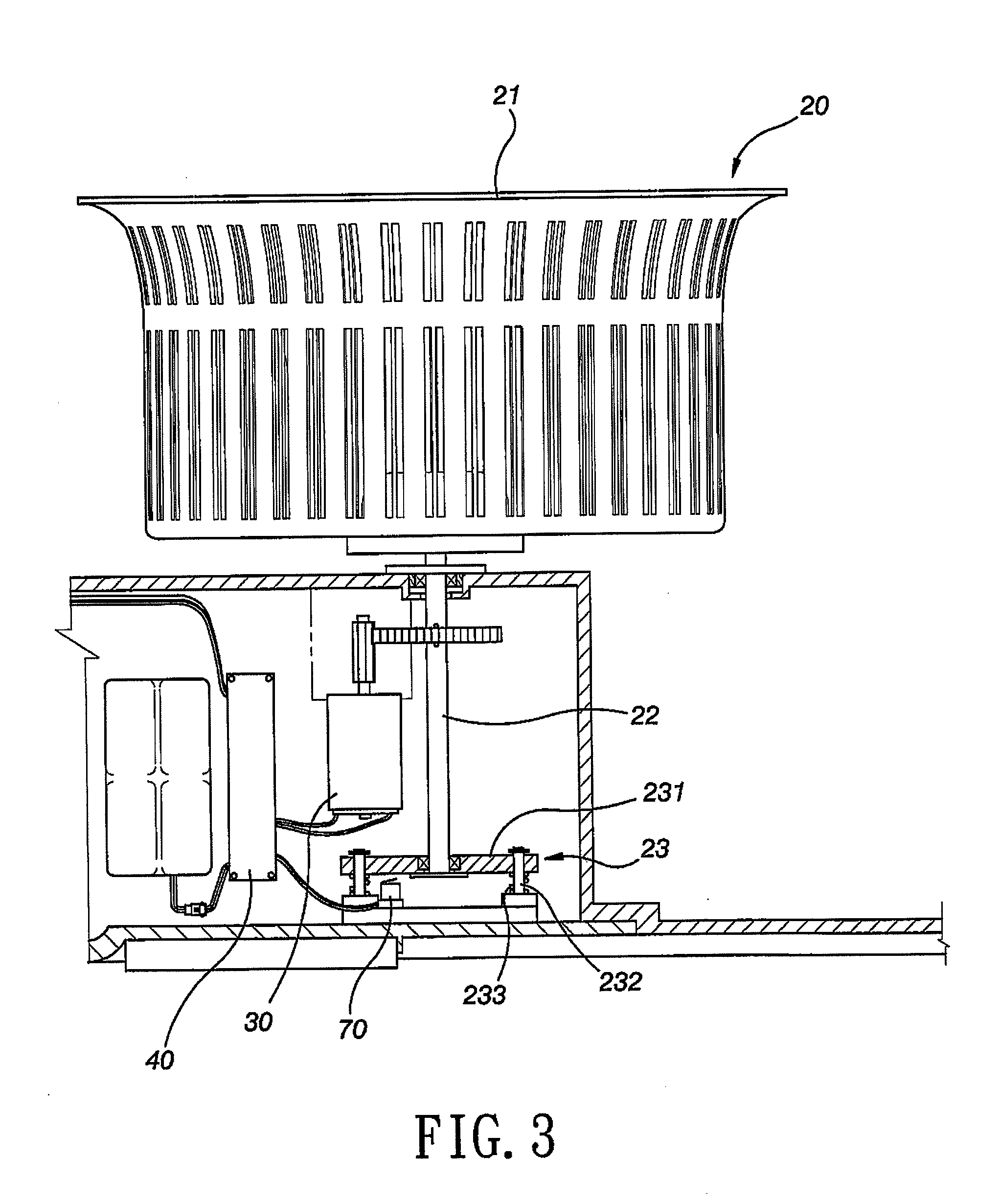
[0025]The dehydration unit 20 is provided in the barrel unit 10 and includes a dehydration basket 21 and a spindle 22 which supports the dehydration basket 21. The spindle 22 is installed on an elastic lifting unit 23 which includes a lifting table 231 for installation of a bottom end of the spindle 22, plural guiding pillars 232 provided on the barrel unit 10 for transfixing the lifting table 231 and at least one elastic element 233 provided between the lifting table 231 and the barrel unit 10. The said elastic element 233 can be a spring or other equivalent element sheathed on the guiding pillar 232 and a lower side of the elastic lifting unit 23 is prov...

third embodiment

[0029]Referring to FIG. 7, it shows a three-dimensional view of the present invention. In the present embodiment, the safety switch 80 is provided in the recharging connection port 60, for example, in an edge inside the recharging connection port 60 as a spring leaf. In addition, a periphery of the recharging connection port 60 is provided with a plug cap 81 which turns on the safety switch 80 when the plug cap 81 is inserted into the recharging connection port 60. This plug cap 81 is also provided with an effect of preventing the recharging connection port 60 from being splashed by water and when the recharging connection port 60 is inserted with a recharging power, the safety switch 80 is also turned on. Besides, the dehydration unit 20 of the present embodiment is further provided with a dehydration plate 24 which can be latched on a top of the dehydration basket 21. When the dehydration plate 24 is latched on the top of the dehydration basket 21, a rag or other wetted small obje...

fourth embodiment

[0030]Referring to FIG. 8, it shows a local cutaway view of the present invention. In the present embodiment, the spindle 22 is made by a magnetic metal and a top end of the spindle 22 is exposed in the dehydration basket 21. The safety switch 80 is a magnetic induction switch and is provided at a periphery of a bottom end of the spindle 22. A bottom end of a mop 100 is provided with a magnet 82 which is attached to the top end of the spindle 22 and enables a bottom end of the spindle 22 to produce a magnetic attraction force, after the mop 100 has been put into the dehydration basket 21; whereas, the safety switch 80 is turned on upon inducing the magnetic attraction force. The safety switch 80 in the drawing is turned on and the starting switch 70 is touched. On the contrary, if the safety switch 80 does not induce the magnetic attraction force, even when the dehydration basket 21 is subjected to a downward force in a certain extent to touch the starting switch 70, the control uni...


PUM


Abstract

A stepping-free electric dehydration barrel includes a barrel unit, a dehydration unit, a motor, a control unit, a rechargeable battery and a recharging connection port. The dehydration unit includes a dehydration basket and a spindle which supports the dehydration basket. The spindle is installed on an elastic lifting unit below which is a starting switch being electrically connected to the control unit. After a user has put a mop into the dehydration basket, he or she only needs to exert a little force to descend the dehydration basket to turn on the starting switch, and then the control unit can drive the motor spinning in a predefined time, thereby achieving an object of easily and rapidly dehydrating.

Description

BACKGROUND OF THE INVENTION[0001]a) Field of the Invention[0002]The present invention relates to a dehydration device, and more particularly to a stepping-free electric dehydration barrel which can be operated without using a foot-stepping method.[0003]b) Description of the Prior Art[0004]An existing dehydration barrel, a dehydration basket of which is driven by a motor, still requires a user to step on a switch paddle to activate the dehydration basket for spinning, wherein as the user needs to step by one foot when using the dehydration barrel, a configuration of standing by one foot will be formed such that the dehydration barrel will be rather inconvenient in usage. In addition, the provision of the paddle will easily arouse curiosity of children to play with.[0005]Accordingly, studies have been undergone by the present inventor for the dehydration barrel with the motor, thereby creating a stepping-free electric dehydration barrel which is completely different from the ordinary ...

Claims


Application Information

Patent Timeline
IPC IPC(8): D06F58/04A47L13/50
CPCD06F49/003A47L13/58
Inventor SHIH, SHU-CHEN
Owner SHIH SHU CHEN
Learn More