
Method and Device for Installing Seamed Industrial Fabric

a technology of industrial fabric and installation method, which is applied in the field of fabric applications, can solve the problems of time-consuming operation of installing fabric onto a twin-wire machin

Active Publication Date: 2011-08-11
HUYCK LICENSOC
View PDF1 Cites 9 Cited by
  • Summary
  • Abstract
  • Description
  • Claims
  • Application Information

AI Technical Summary

Benefits of technology

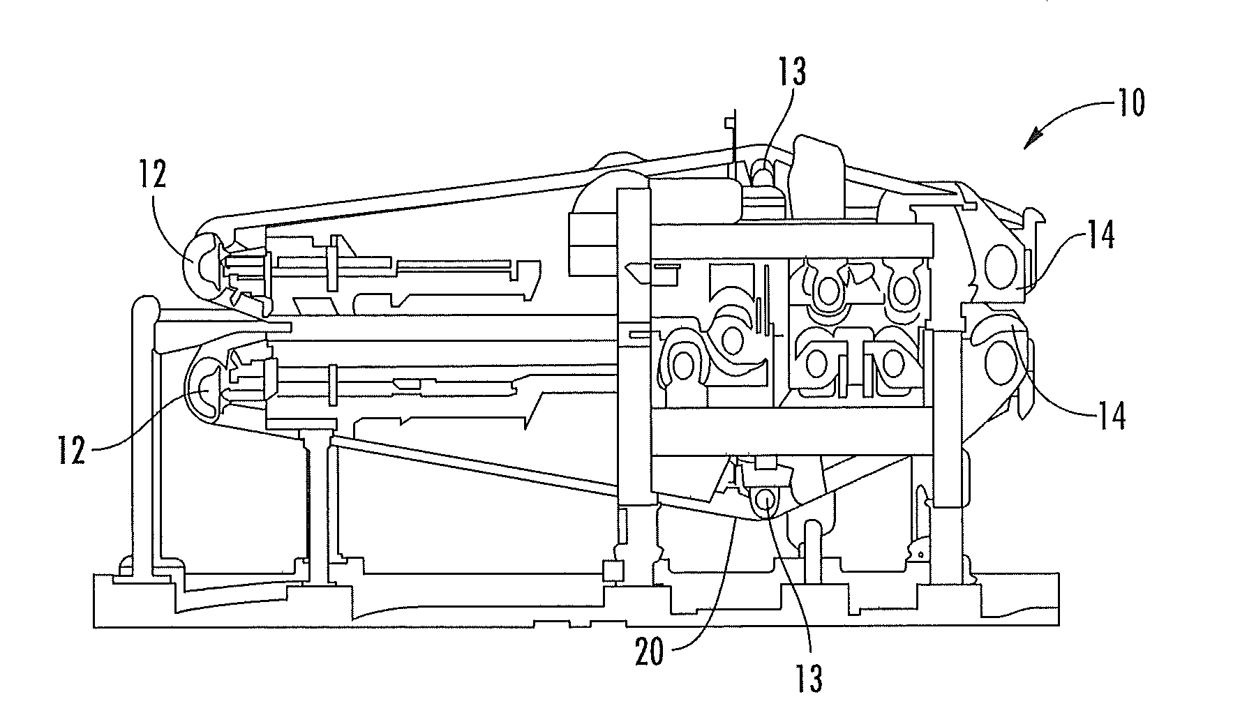
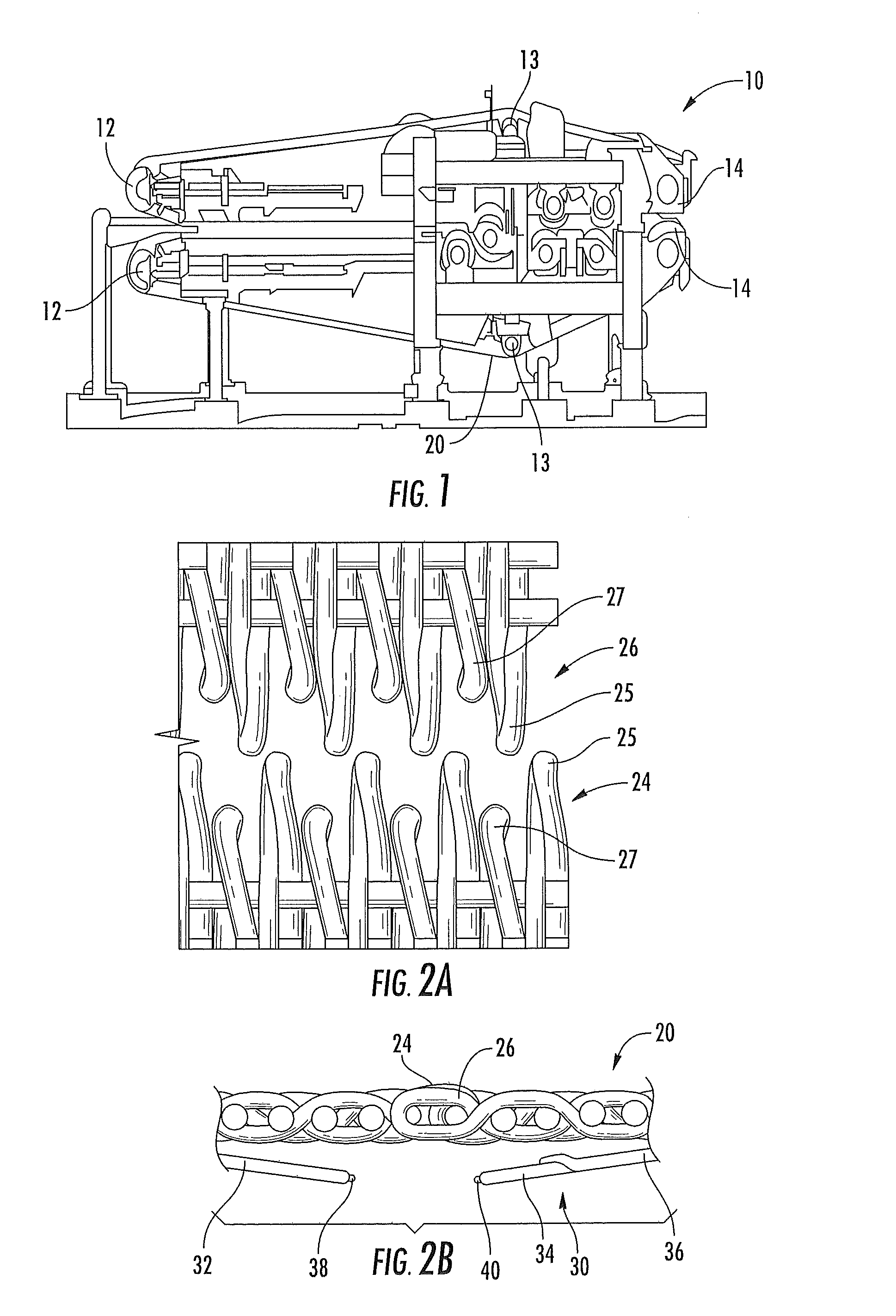
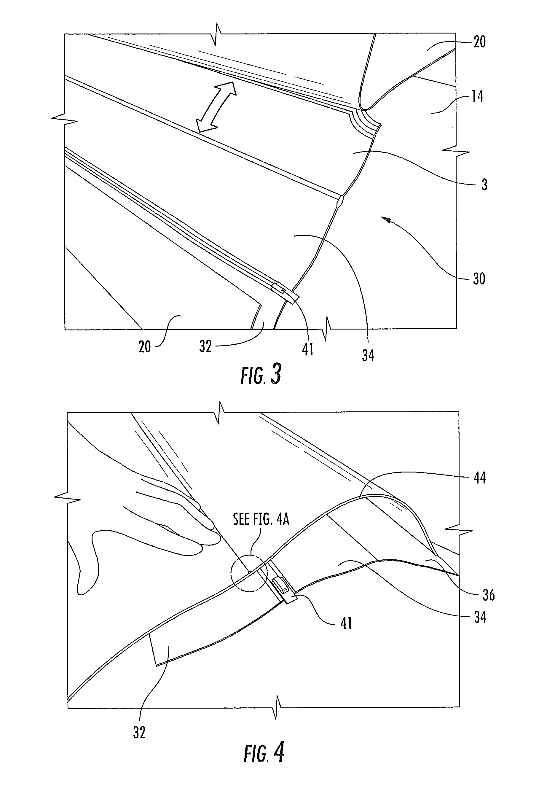
As a first aspect, embodiments of the present invention are directed to a method of installing an industrial fabric on a machine configured to utilize such a fabric. The method comprises as a first step: (a) providing an industrial fabric having: a plurality of machine direction (MD) yarns, the MD yarns forming seam loops at first and second ends of the fabric; a first flap attached adjacent the first end and underlying a first portion of the fabric, the first flap including a first zipper track on an edge portion thereof; and a second flap attached adjacent the second end and underlying a second portion of the fabric, the second flap including a second zipper on an edge portion thereof, the second flap able to stretch elastically such that the distance between its attachment to the second portion of the fabric and the second zipper track can increase when a load is applied to the second zipper track. The method comprises the further steps of: (b) positioning the industrial fabric in the machine; (c) intermeshing the first zipper track and the second zipper track; (d) interdigitating the seam loops on the first end and the second end; and (e) inserting a pintle through the interdigitated seam loops. The use of the flaps can help to align the seam loops, thereby facilitating the subsequent insertion of the pintle, and in particular the insertion of two pintles in a double pin seam.
As a second aspect, embodiments of the present invention are directed to an industrial fabric that is designed for easy seam formation. The fabric comprises: a plurality of MD yarns, the MD yarns forming seam loops at first and second ends of the fabric; a first flap attached adjacent the first end and underlying a first portion of the fabric, the first flap including a first zipper track on an edge portion thereof; and a second flap attached adjacent the second end and underlying a second portion of the fabric, the second flap including a second zipper track on an edge portion thereof. The second flap is able to stretch elastically such that the distance between its attachment to the second portion of the fabric and the second zipper track can increase when a load is applied to the second zipper track.

Problems solved by technology

Installation of the fabric onto a twin wire machine can be a time-consuming operation, particularly in the positioning of the seam loops to receive the pintle.

Method used


Image

  • Method and Device for Installing Seamed Industrial Fabric
  • Method and Device for Installing Seamed Industrial Fabric
  • Method and Device for Installing Seamed Industrial Fabric

Examples


Embodiment Construction

The present invention will now be described more fully hereinafter, in which embodiments of the invention are shown. This invention may, however, be embodied in different forms and should not be construed as limited to the embodiments set forth herein. Rather, these embodiments are provided so that this disclosure will be thorough and complete, and will fully convey the scope of the invention to those skilled in the art. In the drawings, like numbers refer to like elements throughout. Thicknesses and dimensions of some components may be exaggerated for clarity.

Unless otherwise defined, all terms (including technical and scientific terms) used herein have the same meaning as commonly understood by one of ordinary skill in the art to which this invention belongs. It will be further understood that terms, such as those defined in commonly used dictionaries, should be interpreted as having a meaning that is consistent with their meaning in the context of the relevant art and will not be...


PUM


Abstract

A method of installing an industrial fabric on a machine configured to utilize such a fabric includes as a first step: (a) providing an industrial fabric having: a plurality of machine direction (MD) yarns, the MD yarns forming seam loops at first and second ends of the fabric; a first flap attached adjacent the first end and underlying a first portion of the fabric, the first flap including a first zipper track on an edge portion thereof; and a second flap attached adjacent the second end and underlying a second portion of the fabric, the second flap including a second zipper on an edge portion thereof, the second flap able to stretch elastically such that the distance between its attachment to the second portion of the fabric and the second zipper track can increase when a load is applied to the second zipper track. The method comprises the further steps of: (b) positioning the industrial fabric in the machine; (c) intermeshing the first zipper track and the second zipper track; (d) interdigitating the seam loops on the first end and the second end; and (e) inserting a pintle through the interdigitated seam loops. The use of the flaps can help to align the seam loops, thereby facilitating the subsequent insertion of the pintle.

Description

FIELD OF THE INVENTIONThe present invention relates generally to industrial fabric applications, and more particularly to fabrics used in industrial dewatering processes, such as pulp or sludge dewatering.BACKGROUND OF THE INVENTIONIn forming paper and other sheet materials, twin-wire presses have become popular in recent years. These machines differing from a conventional fourdrinier machine in that the formation of the sheet or web takes place between a pair of wires (often formed of a woven fabric) with dewatering accordingly taking place simultaneously in a pair of opposed directions through both of the wires. In this way it is possible to accelerate the dewatering considerably. As a result of this increased efficiency in the dewatering action, a twin-wire section can be made much shorter and in many ways is more economical than a conventional fourdrinier.Fabrics for twin wire machines may be “flat-woven” and formed after weaving into an endless belt, or can be woven in endless ...

Claims


Application Information

Patent Timeline
IPC IPC(8): D21G9/00
CPCD21F1/0054D21G9/00F16G3/02F16G3/003F16G3/00
Inventor BREUER, HANS PETERREITERER, HARALD
Owner HUYCK LICENSOC
Learn More