
Tracking device and method for very large-scale software development projects

a software development and large-scale technology, applied in software maintainance/management, instruments, program control, etc., can solve the problems of limiting the possibility of teams to independently plan work, blurring business priorities, and difficult realization of agile software development components when implementing in large-scale parallel development on a common code base. achieve the effect of facilitating coordination

Inactive Publication Date: 2011-08-04
TELEFON AB LM ERICSSON (PUBL)
View PDF11 Cites 23 Cited by
  • Summary
  • Abstract
  • Description
  • Claims
  • Application Information

AI Technical Summary

Benefits of technology

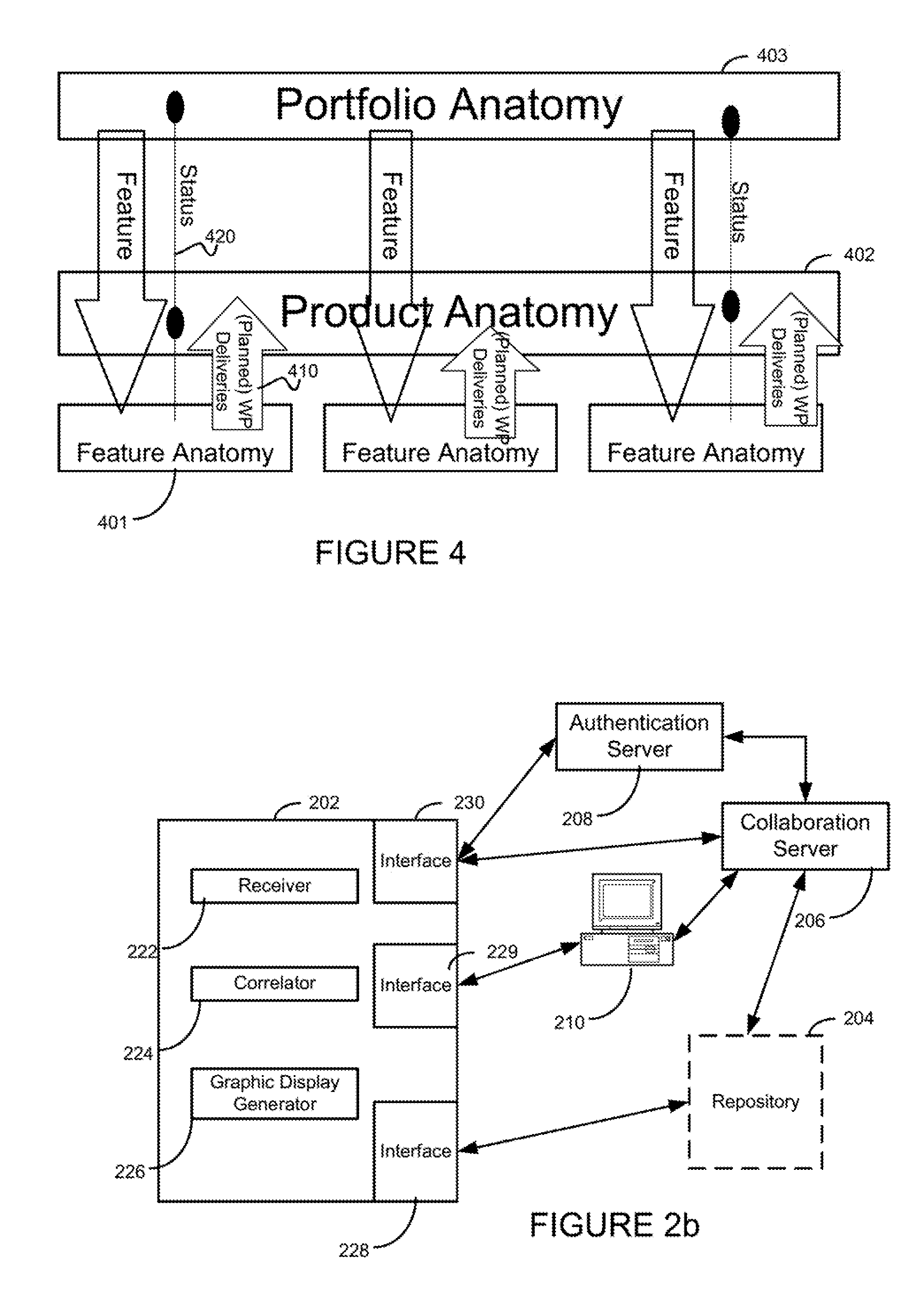
[0022]FIG. 3 depicts an activity overview that facilitates coordi

Problems solved by technology

Adopting ‘Agile’ software development methods and systems to the needs of very large-scale (greater than 100 designers) software projects has many challenges.
Some components of agile software development become extremely hard to realize when implementing in large scale parallel development on a common code base.
Components such as: collaboration; self-organizing teams; and clear priorities (work on most important business items first) can have problems such as technical dependencies in the software or testing that often translate to dependencies between teams, which limit the possibilities of the teams to independently plan the work over time and business priorities get blurred due to timing constraints that teams set between each other.
However, with many teams working in parallel, these applications have very limited possibilities of allowing the teams to identify and manage their dependencies to other teams.
This is a serious impediment that can hinder many large software development projects and organizations to successfully implement Agile software design.

Method used


Image

  • Tracking device and method for very large-scale software development projects
  • Tracking device and method for very large-scale software development projects
  • Tracking device and method for very large-scale software development projects

Examples


Embodiment Construction

[0028]The following definitions of terms will be used throughout the balance of this document.

[0029]Abbreviations

[0030]Anatomy handling device a processor in a server utilizing a particular set of instructions for managing and effecting various operations with respect to internal and external technical dependencies and restrictions of a code development project

[0031]LSV Latest System Version; item on a trunk branch in a distributed revision control system

[0032]Repository Common structured data store used by one or more applications concurrently

[0033]Role A role dedicated to a user which determines the access rights to a particular subset of the functional items in the repository (e.g. stories). Also dedicated views can be displayed based on a specific role.

[0034]RRC IBM Rational Requirement Composer © Requirement handling application

[0035]RS Requirement Specification Document containing a requirement catalog for a certain (commercial) feature of a product

[0036]RTC IBM Rational Team ...


PUM


Abstract

The present invention discloses a method, in a network, of synchronizing a plurality of software development teams, with each team working on an assigned subset of a code development project. A repository comprising all code base of the code development project is provided and each team's assigned subset is correlated with every other team's assigned subset within the code development project. The repository automatically merges all team member inputs so that each subset is linked in a visual representation of each team's assigned subset to stories within connected subsets so that the real-time status of a connected subset may be graphically displayed. A real-time status of each assigned subset, including all correlations between each subset in the project can be determined and any team member, upon demand, can activate and display the visual representation of the real-time status of each subset, the relations between subsets, and the real-time status of the whole development project.

Description

CROSS-REFERENCE TO RELATED APPLICATIONS[0001]This application claims the benefit of U.S. Provisional Application No. 61 / 300,255, filed Feb. 1, 2010, the disclosure of which is incorporated herein by reference.BACKGROUND OF THE INVENTION[0002]The present invention relates to software development. More particularly, and not by way of limitation, the present invention is directed to a system and method for “Agile” software development based on principles of iterative development, where self-organized cross-functional teams elaborate requirements and solutions through collaboration.[0003]Adopting ‘Agile’ software development methods and systems to the needs of very large-scale (greater than 100 designers) software projects has many challenges. Agile software development refers to a group of software development methodologies based on iterative development, where requirements and solutions evolve through collaboration between self-organizing cross-functional teams. Some components of agi...

Claims


Application Information

Patent Timeline
IPC IPC(8): G06F9/44
CPCG06F9/44G06Q10/06G06F8/71
Inventor PACKBIER, RAYMONDKEMP, PETER
Owner TELEFON AB LM ERICSSON (PUBL)
Learn More