Method and system for on-field positioning measurement instruments

a technology of on-field positioning and measurement instruments, applied in the direction of machine supports, domestic objects, applications, etc., can solve the problems of not being able to measure displacements of an order, affecting the end, and machining on the field of mechanical components within the required precision range, etc., to achieve easy and fast removal of connections and low-precision machining operations.

Inactive Publication Date: 2011-08-04
ELLEGI
View PDF7 Cites 3 Cited by
  • Summary
  • Abstract
  • Description
  • Claims
  • Application Information

AI Technical Summary

Benefits of technology

[0024]Thus, the aim of the present invention is to provide an improved method and system for properly on-field locating an interferometric instrument arrangement.
[0025]According to one aspect of the present invention, the above object is achieved by a method according to claim 1, which method provides to use a system, according to claim 3, which can be easily installed, without requiring accurate and time consuming machining operations, and also allowing to easily adjust the flatness and alignment of a plurality of support elements, and to speed up any installation operations or steps, by using a system allowing to quickly and precisely relocate the instruments, at least within the precision limits required by the application, and without the need of using reference or adjusting instruments.
[0026]This system allows moreover to easily adjust the planar arrangement of the instruments and their mutual precise alignment jointly with their supports, an instrument being provided with a pedestal connecting interface not directly coupled to the pedestal or to other interfaces coupled to said pedestal.

Problems solved by technology

In this mode of operation, it is not possible to measure displacements of an order of the wavelength of the radiation being used, typically having centimetric to millimetric values, with an accuracy corresponding to a small fraction thereof, for example, in most common applications, with a precision and accuracy from 0.3 to 0.7 mm.
In fact, different error sources negatively affect the end result, both in a case in which this method is applied for deriving topographic information and in a case in which it is used for differential interferometric applications.
With respect to a proper locating of a suitable installation place, the main difficulties are encountered just at the installation steps, since such an installation must be necessarily performed on a stable support, by using specifically designed assembling features and methods to assure the possibility of always achieving a periodic relocating or a possible future repetition of the involved measurement operations.
The machining on the field of mechanical components within the required precision range, however, is a very complex and difficult operation because of a lacking on site of suitable tools, such as column drilling devices.
In fact, without using such a template, it would not be possible, in a subsequent measurement procedure or campaign, to assemble and relocate the sensor on the plate, which, in turn, is left on the field.
This involves a very complex on-field machining, generally in places such as mountains, in open air and without dedicated manual instruments, with the exception of drilling, threading or honing devices which compel to achieve a tradeoff between the machining speed and precision, anyhow subjected to the skillness of the operator.
Actually, the above mentioned prior system provides to connect on the field three different elements, that is the fixed plate, the template and sensor, thereby making the related operation very complex, since the on-field coupling of the plate to the template must be very precise.

Method used


Image

  • Method and system for on-field positioning measurement instruments
  • Method and system for on-field positioning measurement instruments
  • Method and system for on-field positioning measurement instruments

Examples


Embodiment Construction

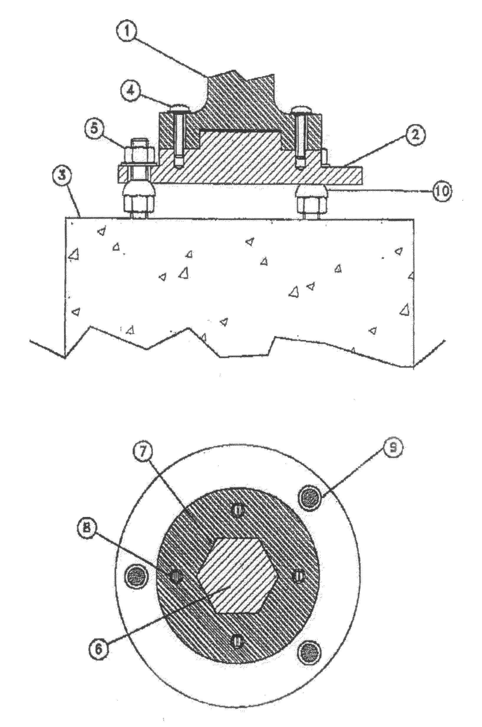
[0037]With reference to the number references of the above mentioned figures, the system according to the invention comprises a concrete pedestal 3, shown in FIG. 3, and stud elements 5 to be used as fixed connecting elements between the pedestal and an intermediate instrument arrangement; in this connection it should be pointed out that this same coupling principle could also be applied to pedestals of any desired materials and to connections of any desired types.

[0038]As shown in FIG. 3, the base of the instrument 1 is coupled to the intermediate system by coupling screws 4 providing movable connections.

[0039]The intermediate system supports the locating elements 6, of hexagonal shape, said element being so machined as to be perfectly plugged-in, with the required precision, into a recess having the same configuration, formed on the instrument base 1.

[0040]The base of said instrument 1 and said intermediate system 2 are then coupled in a laboratory by coupling screws 4 and from co...


PUM


Abstract

A method for quickly and precisely on-field locating and relocating a measurement instrument arrangement, characterized in that said method comprises the steps of:assembling, in a laboratory, said instrument arrangement to an intermediate system thereby providing an instrument arrangement—intermediate system assembly;transporting said instrument arrangement—intermediate system assembly to an installation site;coupling said instrument arrangement—intermediate system assembly to a pedestal by firmly connecting said intermediate system to said pedestal;disconnecting, after use, said instrument arrangement from said intermediate system while leaving said intermediate system coupled to said pedestal; andon-field using again said instrument arrangement by removably reconnecting said instrument arrangement to said intermediate system.

Description

BACKGROUND OF THE INVENTION[0001]The present invention relates to a method and system for on-field positioning radar interferometric instruments, in a very quick, simple and safe manner, and also for easily repositioning said instruments at a different time, while assuring the repeatability of the method with a required repositioning precision.[0002]As is known, interferometric radar methods may be used for recovering position information contained in radar images, for different purposes, in particular for generating elevation digital models of the scene being seen and for measuring displacements of portions of the scene.[0003]Independently from its particular application, the interferometric radar method is based on a quantitative comparing of two images of the same scene taken at positions and time moments which can either coincide or not, depending on the specific application.[0004]Differential interferometry allows, through a comparing of the phases of two time separated acquisi...

Claims


Application Information

Patent Timeline
IPC IPC(8): F16M11/04B23P11/00
CPCB23P11/00Y10T29/49826F16M11/04
Inventor LEVA, DAVIDERIVOLTA, CARLO
Owner ELLEGI
Why Eureka
Try Eureka