Eureka AIR delivers breakthrough ideas for toughest innovation challenges, trusted by R&D personnel around the world.

Method of producing bonded wafer structure with buried oxide/nitride layers

Inactive Publication Date: 2011-07-28
GLOBALFOUNDRIES INC
View PDF17 Cites 4 Cited by
  • Summary
  • Abstract
  • Description
  • Claims
  • Application Information

AI Technical Summary

Benefits of technology

[0005]The present invention provides a method of forming a bonded wafer structure with buried oxide/nitride layers. In this method, the bonding surfaces are either a silicon nitride layer and a silicon oxide layer or two silicon oxide layers. Since the bonding is not between a silicon nitride layer and a silicon layer, standard wafer bond

Problems solved by technology

However, the bond strengths of adhesive wafer bonding are typically lower than those of either fusion or anodic bonding.
In addition, the bonding adhesives typically cannot withstand high temperatures needed for standard complementary metal-oxide-semiconductor (CMOS) processing.
However,

Method used


Image

  • Method of producing bonded wafer structure with buried oxide/nitride layers
  • Method of producing bonded wafer structure with buried oxide/nitride layers
  • Method of producing bonded wafer structure with buried oxide/nitride layers

Examples


Example

[0014]It will be appreciated that for simplicity and clarity of illustration, elements shown in the drawings have not necessarily been drawn to scale. For example, the dimensions of some of the elements may be exaggerated relative to other elements for purpose of clarity.

DETAILED DESCRIPTION OF THE INVENTION

[0015]The present invention will now be described more fully hereinafter with reference to the accompanying drawings in which preferred embodiments of the invention are shown. This invention may, however, be embodied in many different forms and should not be construed as limited to the illustrated embodiments set forth herein. Rather, these embodiments are provided so that this disclosure will be thorough and complete, and will fully convey the scope of the invention to those skilled in the art. Like numerals refer to like features throughout.

[0016]It will be understood that when an element, such as a layer, is referred to as being “on” or “over” another element, it can be direct...


PUM


Abstract

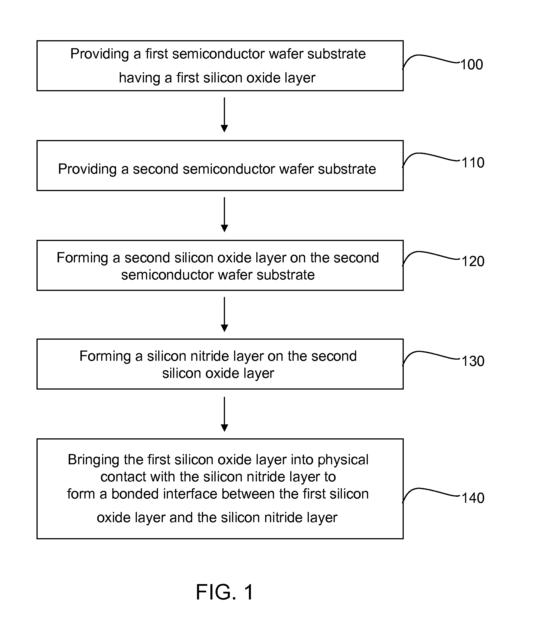
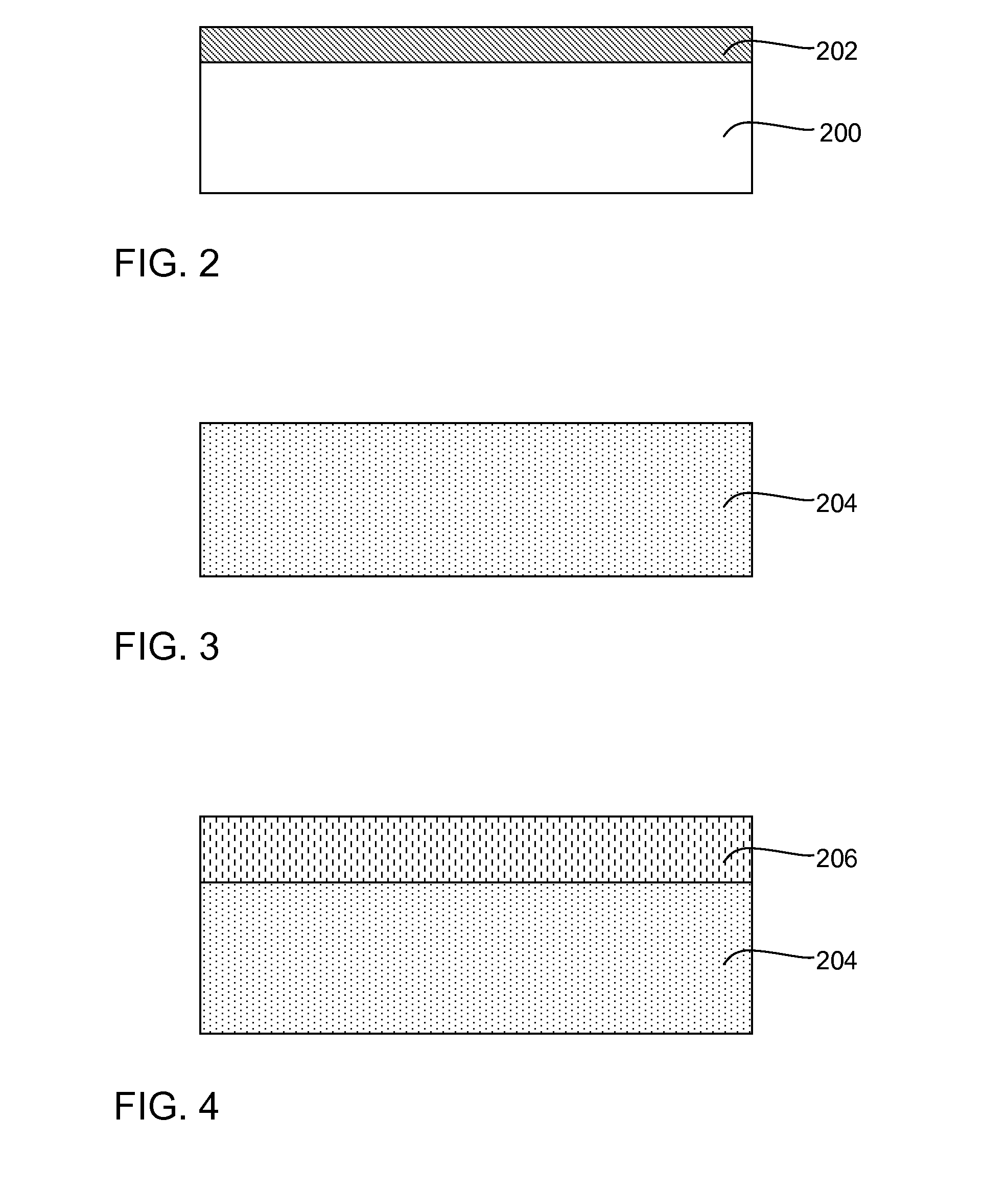
A method of forming a bonded wafer structure includes providing a first semiconductor wafer substrate having a first silicon oxide layer at the top surface of the first semiconductor wafer substrate; providing a second semiconductor wafer substrate; forming a second silicon oxide layer on the second semiconductor wafer substrate; forming a silicon nitride layer on the second silicon oxide layer; and bringing the first silicon oxide layer of the first semiconductor wafer substrate into physical contact with the silicon nitride layer of the second semiconductor wafer substrate to form a bonded interface between the first silicon oxide layer and the silicon nitride layer. Alternatively, a third silicon oxide layer may be formed on the silicon nitride layer before bonding. A bonded interface is then formed between the first and third silicon oxide layers. A bonded wafer structure formed by such a method is also provided.

Description

FIELD OF THE INVENTION[0001]The present invention relates to the field of wafer bonding. More particularly, the invention concerns a method of producing a bonded wafer with buried oxide / nitride layers.BACKGROUND OF THE INVENTION[0002]Advanced designs in semiconductor industry increasingly require a multiple wafer integration strategy where a plurality of wafers are bonded together to form a bonded wafer structure. For example, a semiconductor-on-insulator (SOI) substrate may be formed by a wafer bonding process in which two semiconductor wafers, one of which includes a layer of insulating material at the bonding surface, are brought into intimate contact with each other. The bonded wafer is then ground mechanically and polished to form a SOI layer. Alternatively, the wafer bonding process may utilize a layer transfer (for example SMARTCUT or Silicon Gensis) process in which ions of hydrogen or a noble gas or the like are implanted into a first wafer and after bonding the first wafer...

Claims


Application Information

Patent Timeline
IPC IPC(8): H01L29/06H01L21/762
CPCH01L21/76256
Inventor PFEIFFER, GERDYIN, HAIZHOUSPROGIS, EDMUND J.IYER, SUBRAMANIANREN, ZHIBINPARK, DAE-GYUGLUSCHENKOV, OLEG
Owner GLOBALFOUNDRIES INC
Why Eureka
Eureka Blog
Learn More