High resolution non-contacting multi-turn position sensor

a multi-turn position, high-resolution technology, applied in the field of sensors, can solve the problems of ambiguity in output and limited angular sensors, and achieve the effect of convenient removal

Active Publication Date: 2011-07-21
BOURNS INC
View PDF1 Cites 24 Cited by
  • Summary
  • Abstract
  • Description
  • Claims
  • Application Information

AI Technical Summary

Benefits of technology

[0006]In certain embodiments, the present disclosure relates to a device having a housing. The device further includes a rotatable shaft having a longitudinal axis, wherein at least a portion of the shaft is within the housing. The device further includes a movable carrier disposed substantially within the housing and coupled to the shaft such that rotation of the shaft results in linear motion of the carrier along the longitudinal axis. The device further includes a magnet disposed on the carrier so as to move with the carrier such that a range of rotation of the shaft results in a range of linear motion of the magnet along the longitudinal axis. The magnet can be oriented such that the magnet's magnetization axis is substantially perpendicular to the longitudinal axis. The device further includes a magnetic sensor circuit disposed substantially within the housing, where the circuit is configured to uniquely determine position of the magnet anywhere within the range of linear motion of the magnet thereby allowing determination of rotational position of the shaft within the range of rotation.
[0021]In certain embodiments, the sensor further includes a shield configured to provide shielding to at least the sensor assembly from external field or radiation. In certain embodiments, the shield is configured to attenuate X-ray, gamma radiation, charged particle radiation, or neutrons. In certain embodiments, the sensor assembly is disposed within the upper portion of the U-shaped housing. In certain embodiments, the shield substantially conforms to the upper portion of the U-shaped housing so as to provide shielding effect for external field of radiation that is generally directional. In certain embodiments, the housing and the shield are configured such that the shield is readily removable.

Problems solved by technology

However, such angular sensors are either limited by one rotation (360 degrees) or have ambiguity in output when allowed to sense more than one turn of the rotating device.

Method used


Image

  • High resolution non-contacting multi-turn position sensor
  • High resolution non-contacting multi-turn position sensor
  • High resolution non-contacting multi-turn position sensor

Examples


Embodiment Construction

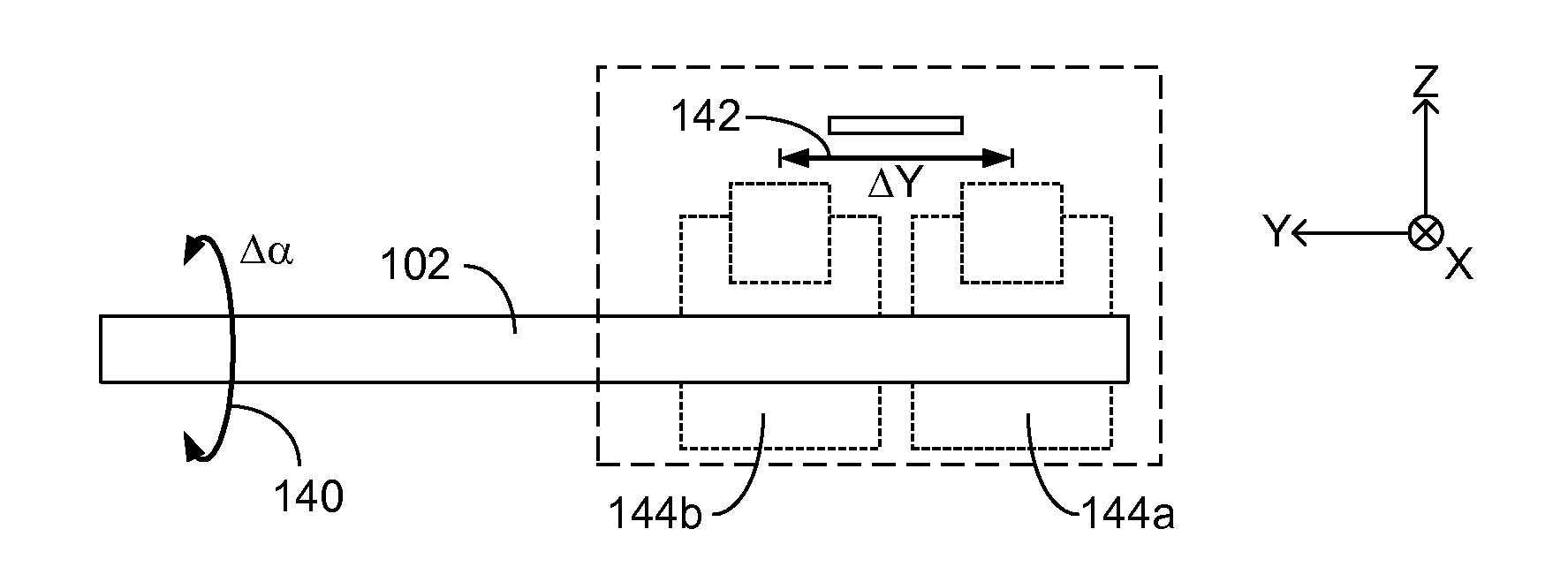
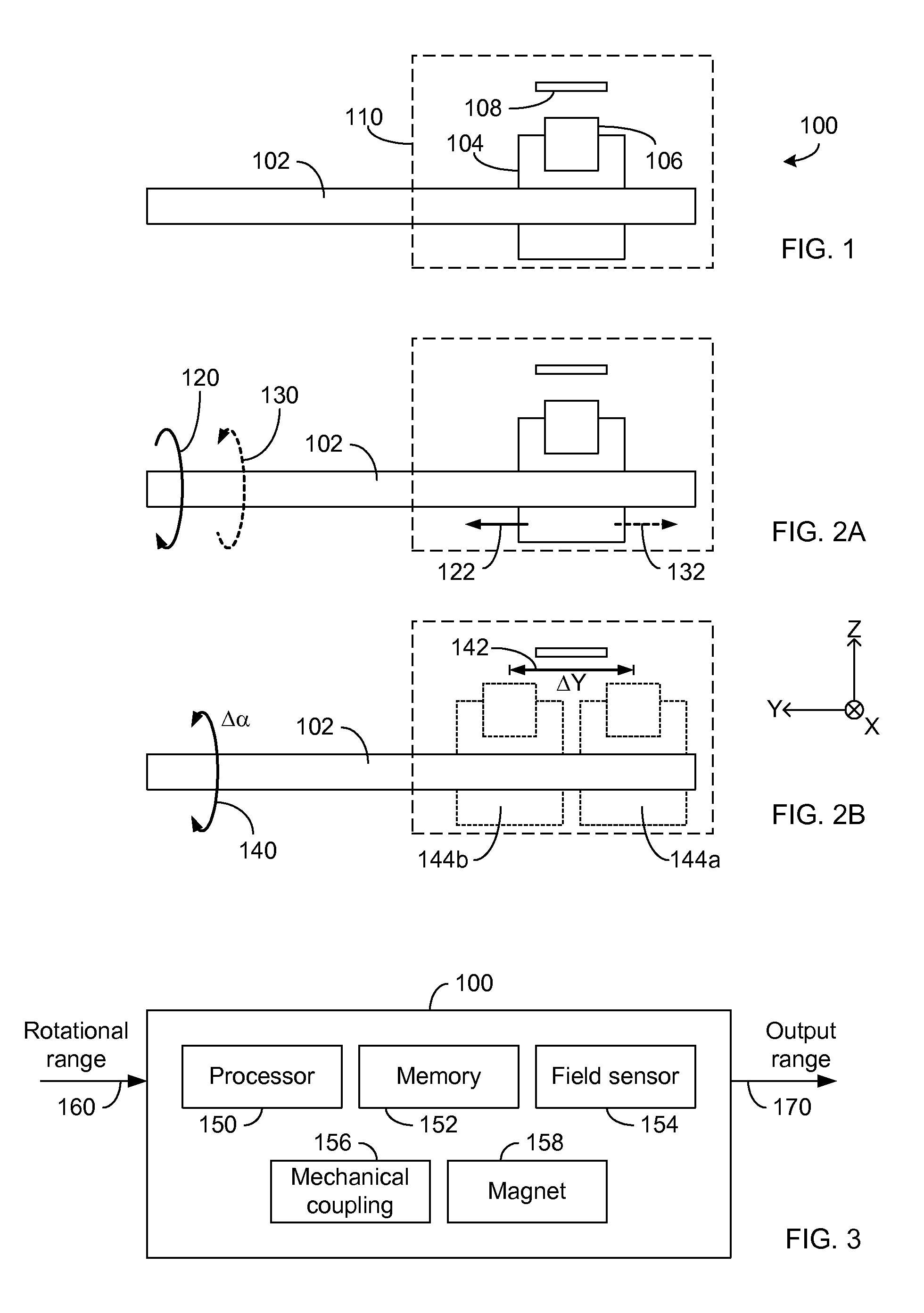
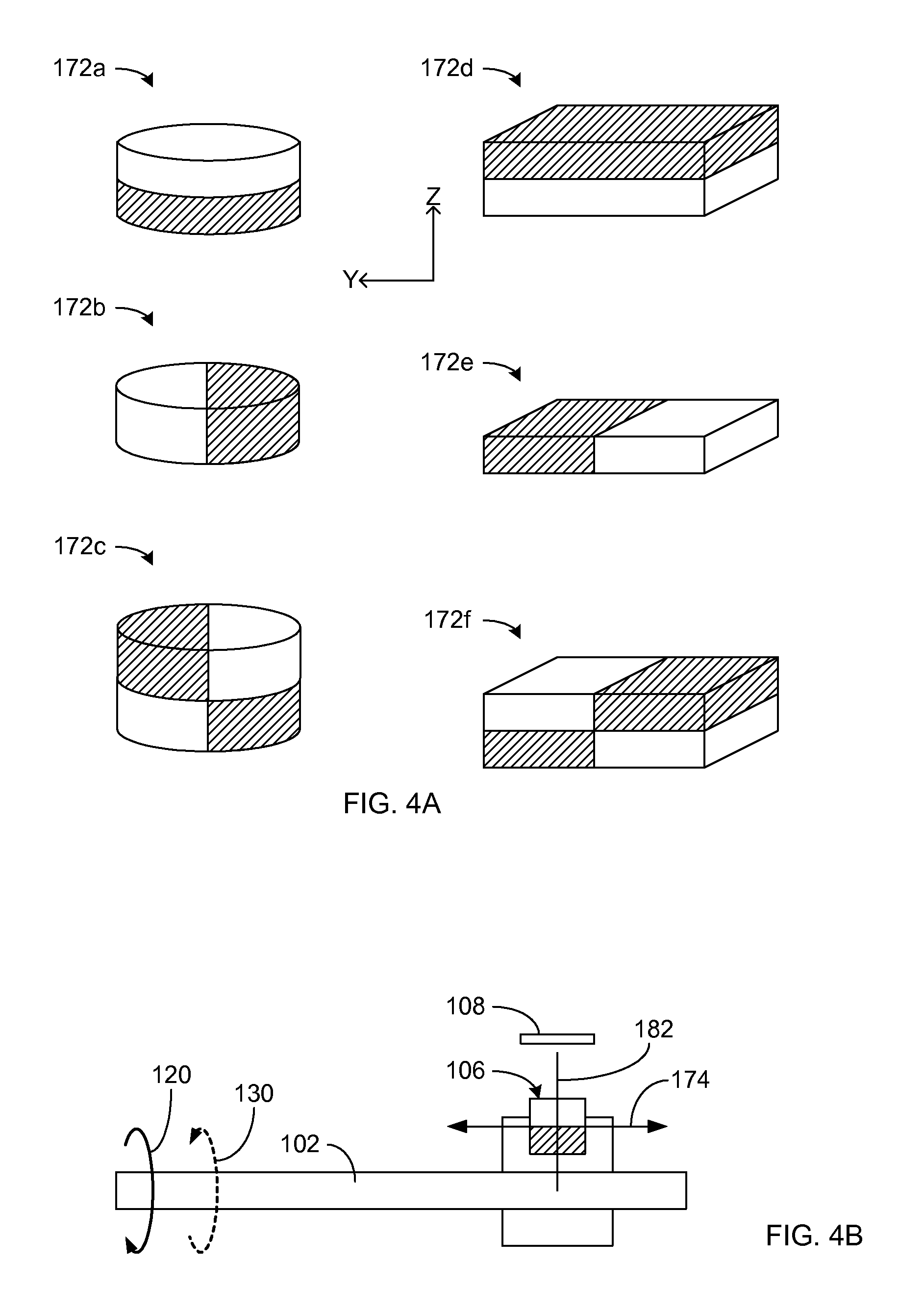
[0047]The present disclosure generally relates to a rotational position sensor. As described herein, one or more embodiments of the rotational position sensor can have advantageous features. For example, the sensor can be configured to provide a multi-turn input capability, and the number of turns for such an input can be selected and programmed. Accordingly, rotational position resolution of the sensor can be adjusted from relatively coarse resolution to relatively high or fine resolution. In another example, the sensor can be configured to provide such functionality with non-contacting arrangement between a sensing element and a sensed element. Accordingly, various mechanical issues typically associated with physically contacting configurations can be avoided.

[0048]In certain embodiments of the present disclosure, the rotational position sensor transforms rotational motion of a rotating object (such as a shaft) into a translational motion of a sensed element. A sensing element is ...


PUM


Abstract

Disclosed are systems and methods for effectively sensing rotational position of an object. In certain embodiments, a rotational position sensor can include a shaft configured to couple with the rotating object. The shaft can be configured to couple with a magnet carrier such that rotation of the shaft yields translational motion of the carrier. A magnet mounted to the carrier also moves longitudinally with respect to the axis of the shaft, and relative to a magnetic field sensor configured to detect the magnet's longitudinal position. The detected longitudinal position can be in a range corresponding to a rotational range of the shaft, where the rotational range can be greater than one turn. In certain embodiments, the rotational position sensor can include a programmable capability to facilitate ease and flexibility in calibration and use in a wide range of applications.

Description

BACKGROUND[0001]1. Field of the Invention[0002]The present disclosure generally relates to the field of sensors, and more particularly, to systems and methods for sensing angular position of an object such as a rotatable shaft.[0003]2. Description of the Related Art[0004]In many mechanical and / or electromechanical devices, it is desirable to accurately determine a state of a rotating object. For example, a rotating object such as a jackscrew imparts linear motion to another object by its rotation. In many situations, it is desirable to accurately determine the linearly moving object's location. Such determination can be based on knowing the angular position of the rotating object.[0005]In some devices, angular position determination can be measured by an angular sensor. However, such angular sensors are either limited by one rotation (360 degrees) or have ambiguity in output when allowed to sense more than one turn of the rotating device.SUMMARY[0006]In certain embodiments, the pres...

Claims


Application Information

Patent Timeline
IPC IPC(8): G01B7/30
CPCG01D5/14
Inventor BOGOS, EUGENWEHLMAN, PERRYNGUYEN, THANH VINH
Owner BOURNS INC
Why Eureka
Try Eureka