Lamp Support Structure for Lamp Tubes

a lamp tube and support structure technology, applied in the direction of lighting device details, lighting support devices, lighting and heating apparatuses, etc., to achieve the effect of facilitating the adjustment of the assembly angle of the lamp tub

Inactive Publication Date: 2011-07-14
MAI MAO KAI
View PDF10 Cites 3 Cited by
  • Summary
  • Abstract
  • Description
  • Claims
  • Application Information

AI Technical Summary

Benefits of technology

[0005]In view of the above-described circumstances, it is a primary object of the present invention to provide a lamp support structure convenient for the user to repair or replace lamp tubes.
[0007]In the present invention, a disk may be further provided, and at least third and fourth slots and fifth and sixth slots are provided on the disk corresponding to the first and second slots; wherein the third slot and the fourth slot are located on the same first center line and arranged perpendicular to each other, and the fifth slot and the sixth slot are located on the same second center line and arranged perpendicular to each other; the third and fourth slots (or the fifth and sixth slots) can be optionally used to screw and secure the disk to an assembly main body such as a ceiling or a wall, and then the fifth and sixth slots (or the third and fourth slots) are used to secure the lamp support to the lower portion of the disk so as to achieve the purpose of facilitating the adjustment of the assembly angle of the lamp tube.

Problems solved by technology

The structural strength of the threaded holes on the assembly main body will be relatively weakened particularly after multiple and repeated disassembly and assembly, so that the threaded holes cannot provide the original grasping force, which is more likely to cause danger when the lighting fixture accidentally drops down.

Method used


Image

  • Lamp Support Structure for Lamp Tubes
  • Lamp Support Structure for Lamp Tubes
  • Lamp Support Structure for Lamp Tubes

Examples


Embodiment Construction

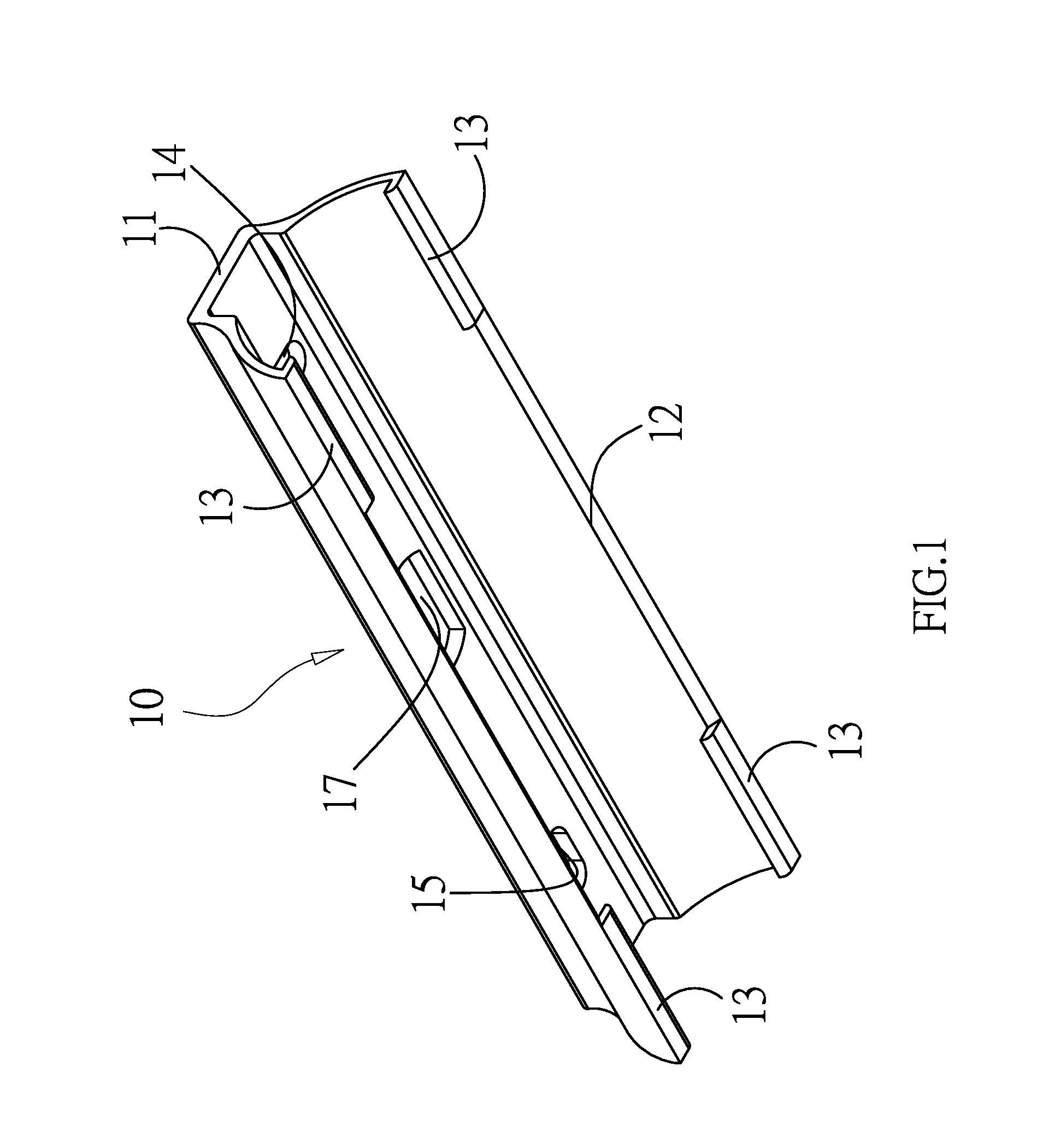
[0014]The present invention aims to provide a lamp support structure capable of increasing the convenience and applicability in mounting lamp tubes. As illustrated in FIG. 1, a lamp support 10 of the present invention comprises a keel 11 having a predetermined length as the main body, two arc-shaped extensions 12 provided on two sides of the keel, at least one pair of inwardly protruding lips 13 correspondingly provided on bottom edges of the arc-shaped extensions 12, and a first slot 14 and a second slot 15 provided on the ridge of the keel 11 and arranged perpendicular to each other.

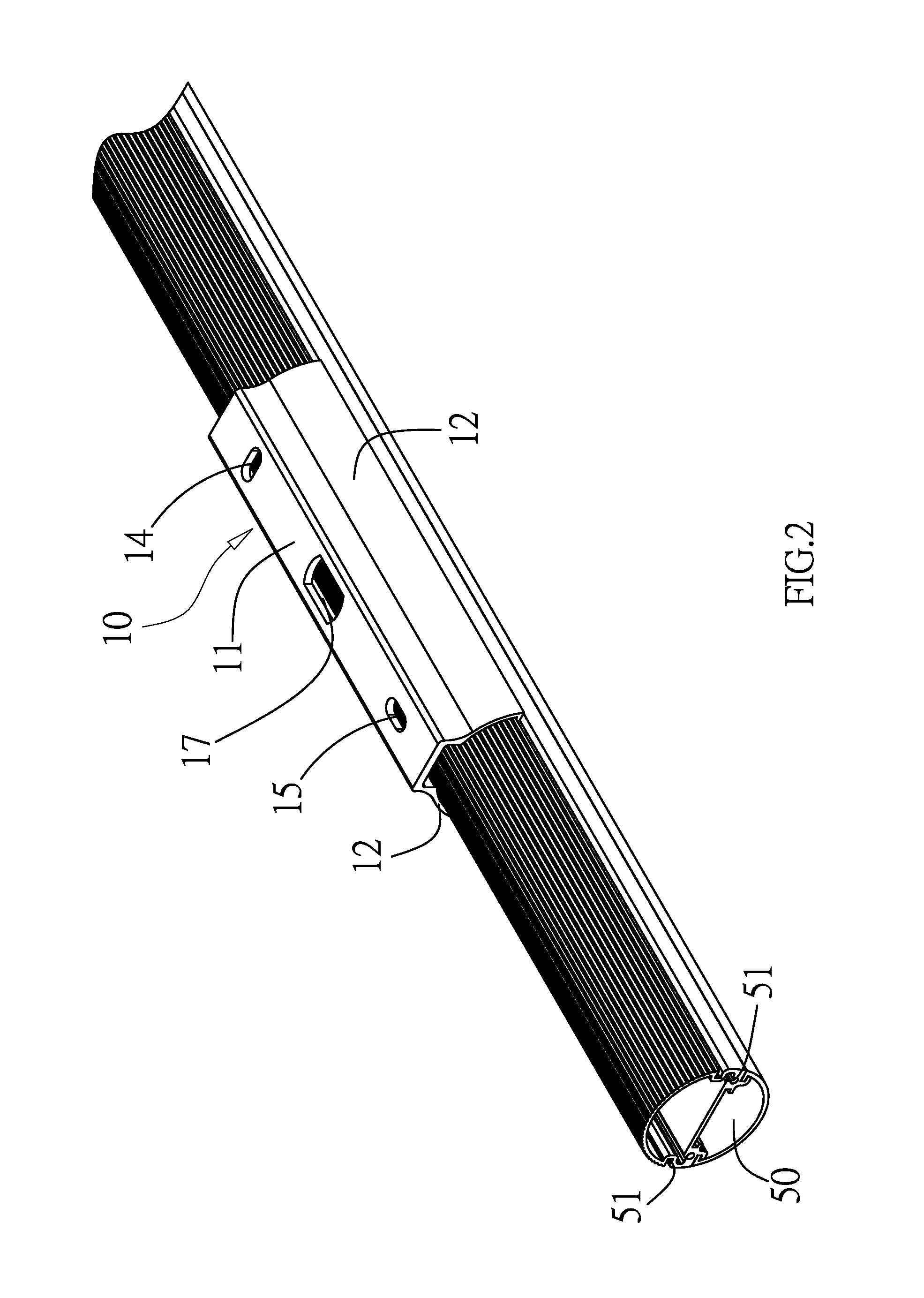
[0015]As illustrated in FIGS. 2 and 3, when the lamp support 10 of the present invention is in use, The first and second slots 14, 15 can allow for the passage of screws 30 so that the screws 30 can be used to secure the entire lamp support 10 to an assembly main body 40 such as a ceiling or a wall; and the lips 13 correspondingly fit into grooves 51 on both sides of a lamp tube 50 whereby the lamp tub...


PUM


Abstract

A lamp support of the present invention comprises a keel as the main body, two arc-shaped extensions provided on two sides of the keel, inwardly protruding lips correspondingly provided on bottom edges of the arc-shaped extensions, and first and second slots provided on the ridge of the keel and arranged perpendicular to each other. The first and second slots can allow for the passage of screws so that the screws can be used to secure the entire lamp support to an assembly main body such as a ceiling or a wall; and the lips correspondingly fit into grooves on both sides of a lamp tube whereby the lamp tube is pushed into a predetermined position to secure the lamp tube to the assembly main body such as a ceiling or a wall.

Description

FIELD OF THE INVENTION[0001]The present invention relates to a lamp tube mounting structure, and more particularly to an improvement in lamp support structures capable of increasing the convenience and applicability in mounting lamp tubes.BACKGROUND OF THE INVENTION[0002]Nowadays, direct lighting fixtures are principally used as general room illumination sources. For example, fluorescent tubes are mounted on a ceiling and light emitted from the fluorescent tubes directly illuminates downwards. In modern society, with continuing technological progress, the technology of lighting systems is developing rapidly. Besides, as the global energy issue becomes increasingly stressed and all the governments in the world will gradually forbid the use of incandescent bulbs in the future, light-emitting diodes (LEDs), relying on the advantages of high efficiency, energy saving and light modulation property, have gradually dominated the lighting market. Their applications in street lamps, vehicle ...

Claims


Application Information

Patent Timeline
IPC IPC(8): F21V29/00F21V21/00
CPCF21V19/009
Inventor MAI, MAO-KAI
Owner MAI MAO KAI
Why Eureka
Try Eureka