
Suspension arrangement for clothes washing machine

Inactive Publication Date: 2011-07-14
WHIRPOOL SA
View PDF12 Cites 26 Cited by
  • Summary
  • Abstract
  • Description
  • Claims
  • Application Information

AI Technical Summary

Benefits of technology

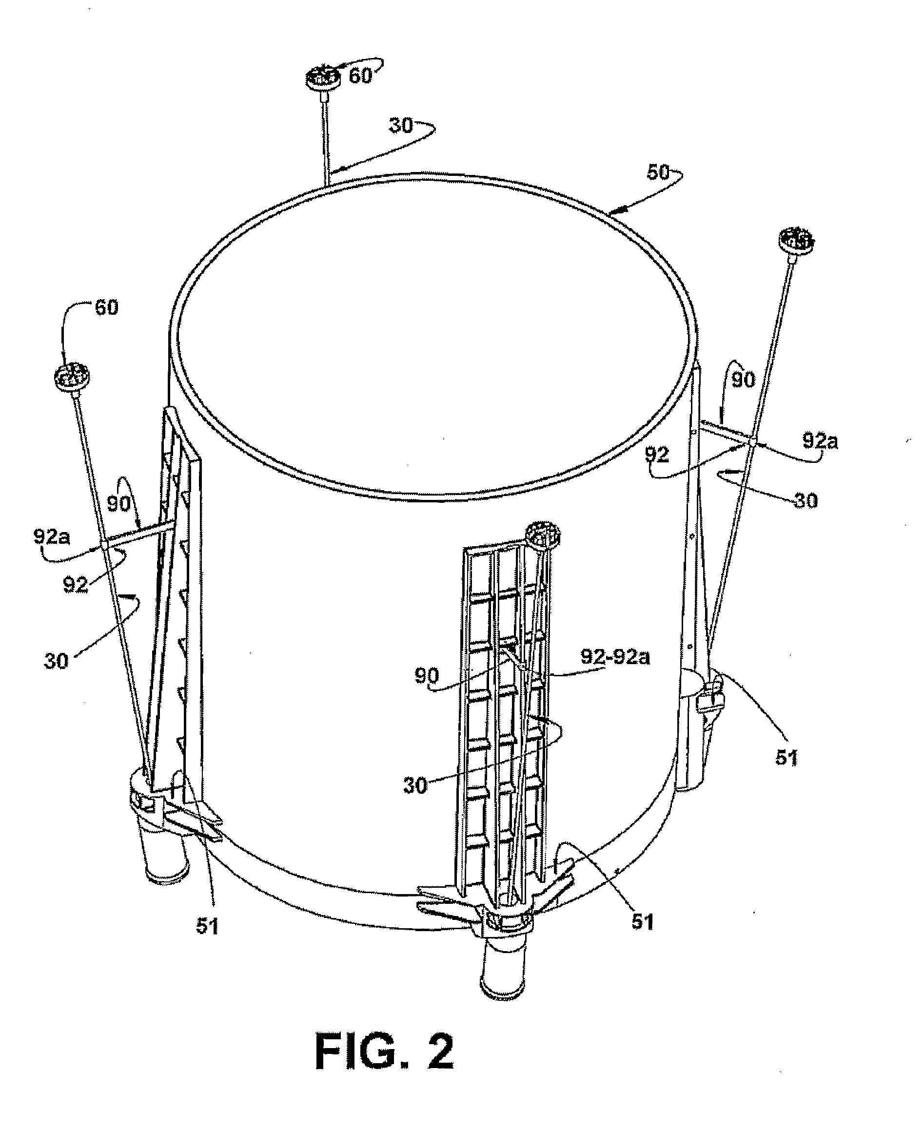
[0009]In view of the drawbacks and operational limitations of said known suspension arrangements, it is an objective of the present invention to provide a suspension arrangement that permits a substantial increase in its capacity to dissipate the vibratory energy produced by the eccentric masses in movement during machine operation, preventing said energy from being transmitted to the structural cabinet at an intensity sufficient to produce operational shocks between the tank and the structural cabinet and also the displacement of the latter over the floor (walking).
[0010]It is a further objective of the present invention to provide a suspension arrangement as mentioned above that is simple to build and to apply to the suspension means, without requiring constructive changes to the tank and the machine's structural cabinet.
[0014]The solution now proposed leads to a substantial increase in its capacity to absorb the vibratory (kinetic) energy principally during the spinning phase, preventing said energy from being transmitted to the structural cabinet, avoiding shocks between the tank and the structural cabinet and also the displacement of the latter over the floor (walking).

Problems solved by technology

Although widely used and still capable of dissipating a certain degree of vibratory energy generated by the masses in movement, reducing transfer thereof to the structural cabinet, these known suspension arrangements are not capable of providing the desired degree of dissipation of dynamic energy during operations, particularly spinning, with a certain clothes load irregularly or unevenly positioned inside the basket.
In such situations, an undesirable portion of vibratory energy generated by the eccentric mass being turned is transmitted to the structural cabinet, making it, depending on the uneven load, vibrate at an intensity that may be sufficient to cause it to walk over the floor, even in the suspension rod construction formed in multiple sequentially-articulated rod extensions.
Besides the drawback referred to above, the suspension arrangements mentioned allow, under certain displacement conditions of clothing load in the basket, that the tank vibrates in such a way that it bangs into the cabinet, in view of its limited capacity to dissipate the vibratory energy generated.
Any collision of the tank with the cabinet causes intensely loud noises and also subjects the machine components to damaging impacts that further contribute to dislodge the cabinet from its position.

Method used


Image

  • Suspension arrangement for clothes washing machine
  • Suspension arrangement for clothes washing machine
  • Suspension arrangement for clothes washing machine

Examples


Embodiment Construction

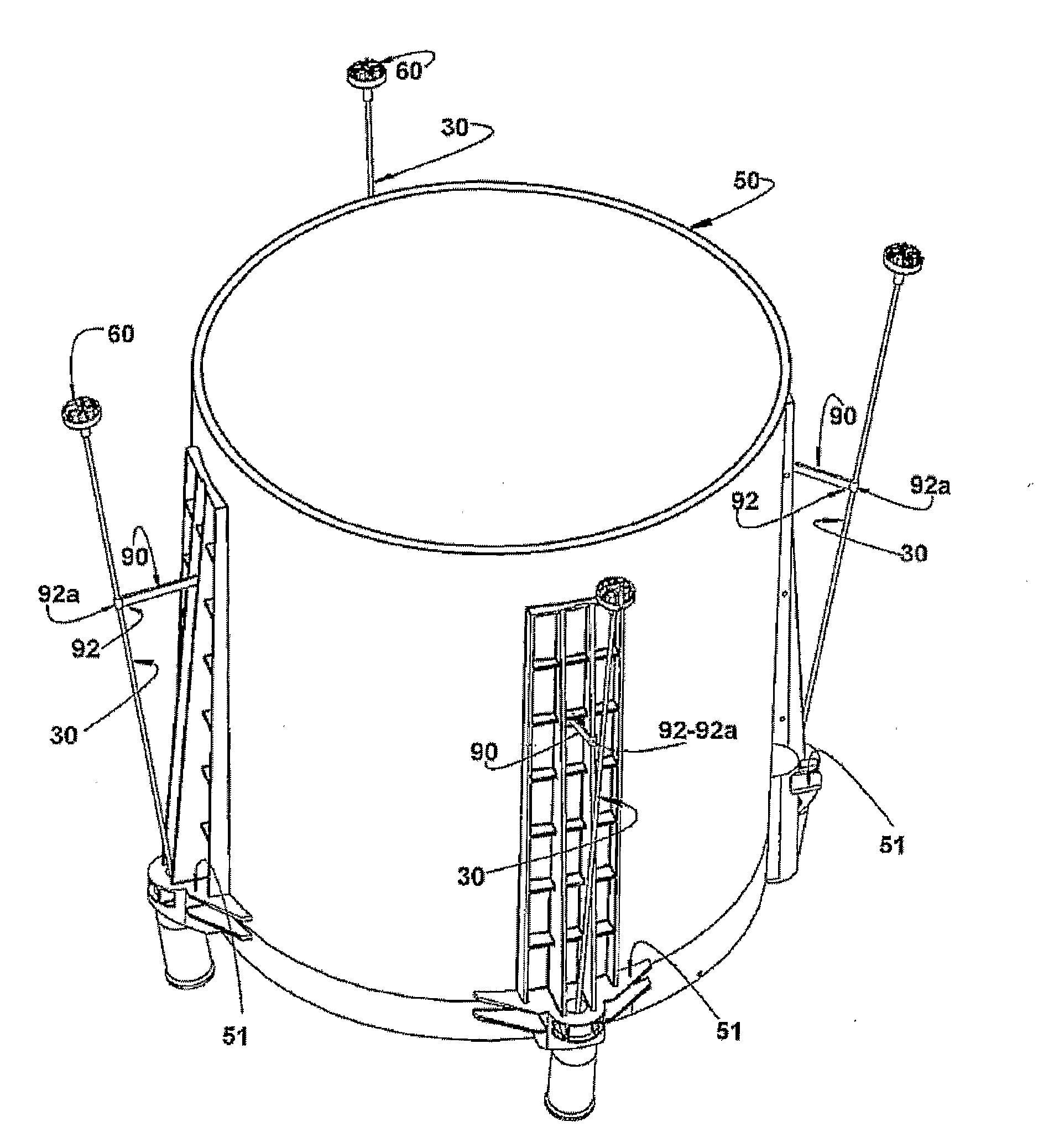
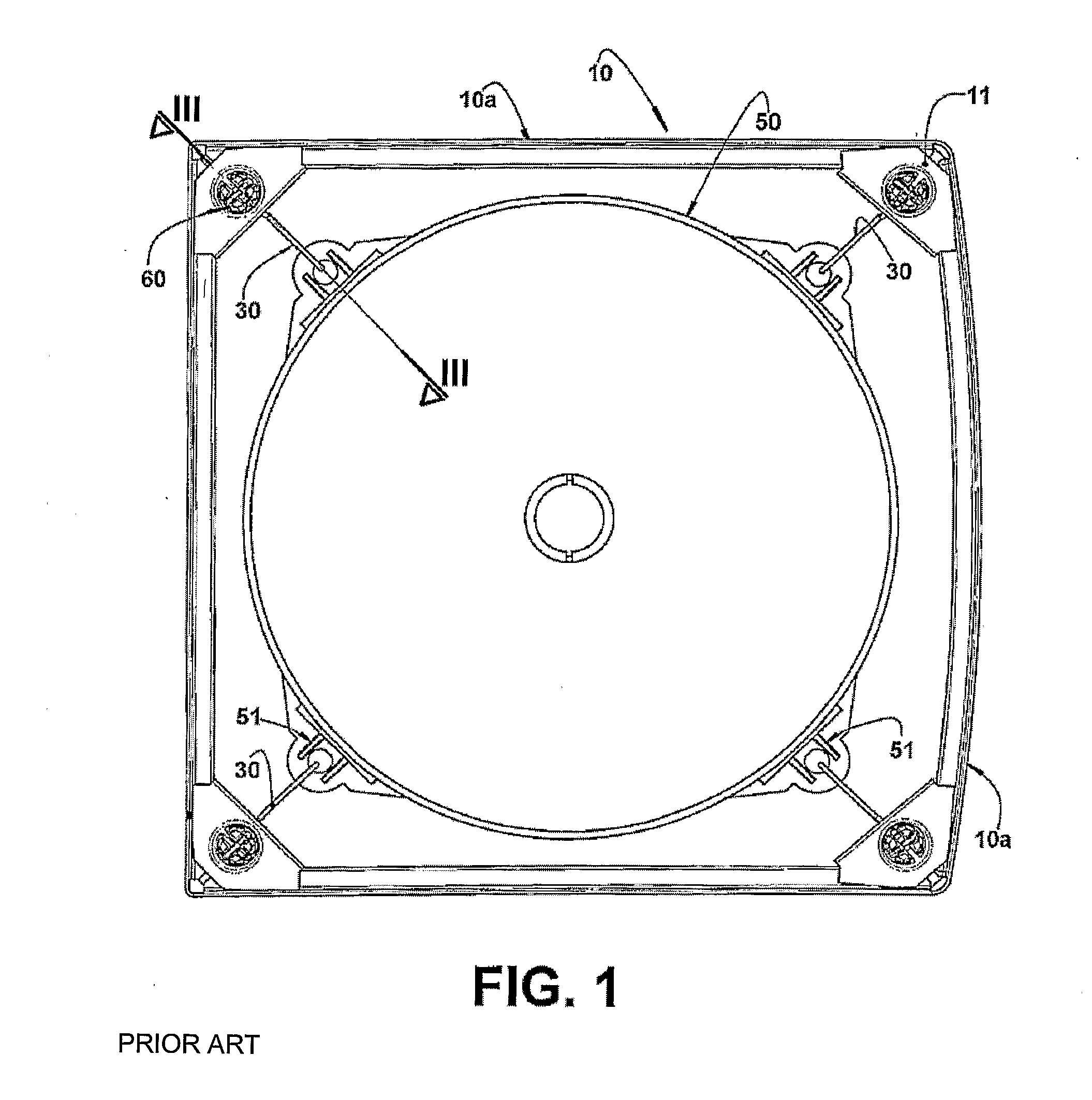
[0024]As mentioned above and also illustrated in the drawings appended hereto, the invention refers to a clothes washing machine, preferably top loading, but also to a front loading, horizontal shaft washing machine, said machine comprising a basic structural cabinet 10, generally defined by a tubular-shaped body, generally polygonal in section and to stand on a floor (not illustrated). The structural cabinet 10 can be built in different ways using different materials, but preferably, takes on the shape of a tubular body comprising a surrounding rib 10a, generally metal plates and, in the configuration illustrated, it is formed by portions of front, rear and opposed side walls.

[0025]The structural cabinet 10 incorporates, on top, generally next to the vertices of its polygonal transversal section, a horizontal rim 11, welded or otherwise fixed internally to the structural cabinet 10, next to the upper edge thereof, each horizontal rim 11 defining a support on which a respective susp...


PUM


Abstract

The suspension arrangement for the clothes washing machine is defined by a plurality of suspension rods, each comprising a slim and flexible stem having an upper end coupled to a structural cabinet and a lower end coupled to a tank to be suspended inside the structural cabinet. The arrangement also provides for a plurality of radial rods, having an inner end coupled to a median side region of the tank, and an outer end coupled to a facing median region of a respective suspension rod so as to transmit to each respective suspension rod at least part of the radial displacement of the tank during machine operation, so as to cause a corresponding elastic deformation, by flexion, on the respective suspension rod.

Description

FIELD OF THE INVENTION[0001]The present invention refers to a suspension arrangement for the tank containing washing liquid of a washing machine, particularly a vertical shaft, top-loader washing machine, in which the tank is suspended inside a structural cabinet of the machine, by suspension means, at least partially and elastically deformable, to dissipate vibratory energy resulting from the tank oscillation when the perforated basket is spun or of an agitator / thrust assembled inside the tank, to move a clothing load during washing and spinning operations performed by the machine.BACKGROUND OF THE INVENTION[0002]In washing machines of the type referred to above, washing operations of clothing loads contained in the basket are performed by spinning the basket on the horizontal shaft of front loading machines and by the turning of the agitator / thrust on the vertical shaft of top loading machines, wherein the turning of the basket or agitator / thrust is in a single direction when appl...

Claims


Application Information

Patent Timeline
IPC IPC(8): D06F37/00
CPCD06F37/268D06F37/24
Inventor DE ANGELO SANCHEZ, JOSE PAULODE OLIVEIRA MUNHOZ, ERICO
Owner WHIRPOOL SA
Learn More