Reduced water mist generating device and electric apparatus
- Summary
- Abstract
- Description
- Claims
- Application Information
AI Technical Summary
Benefits of technology
Problems solved by technology
Method used
Image
Examples
configuration example 1
Specific Configuration Example 1
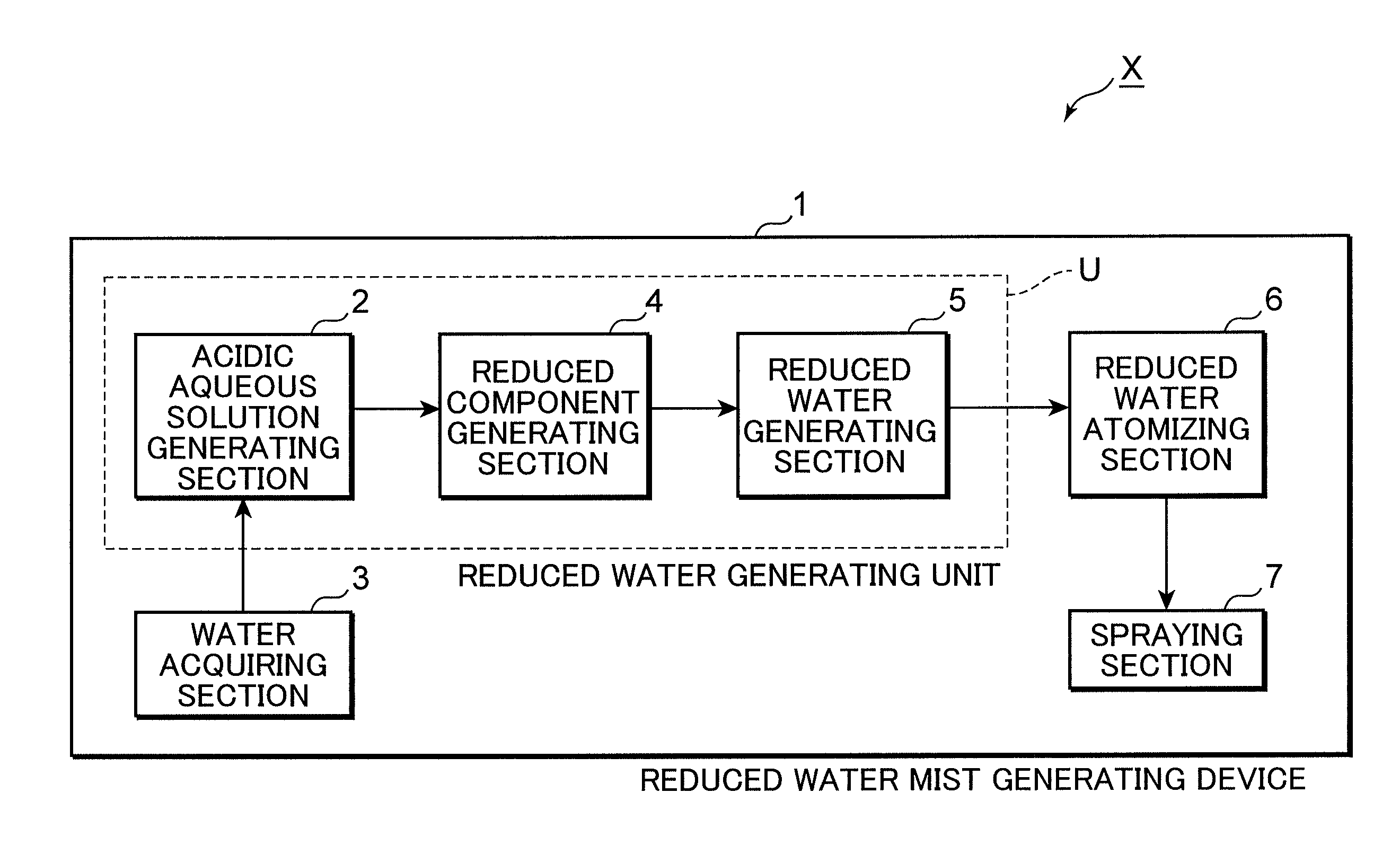
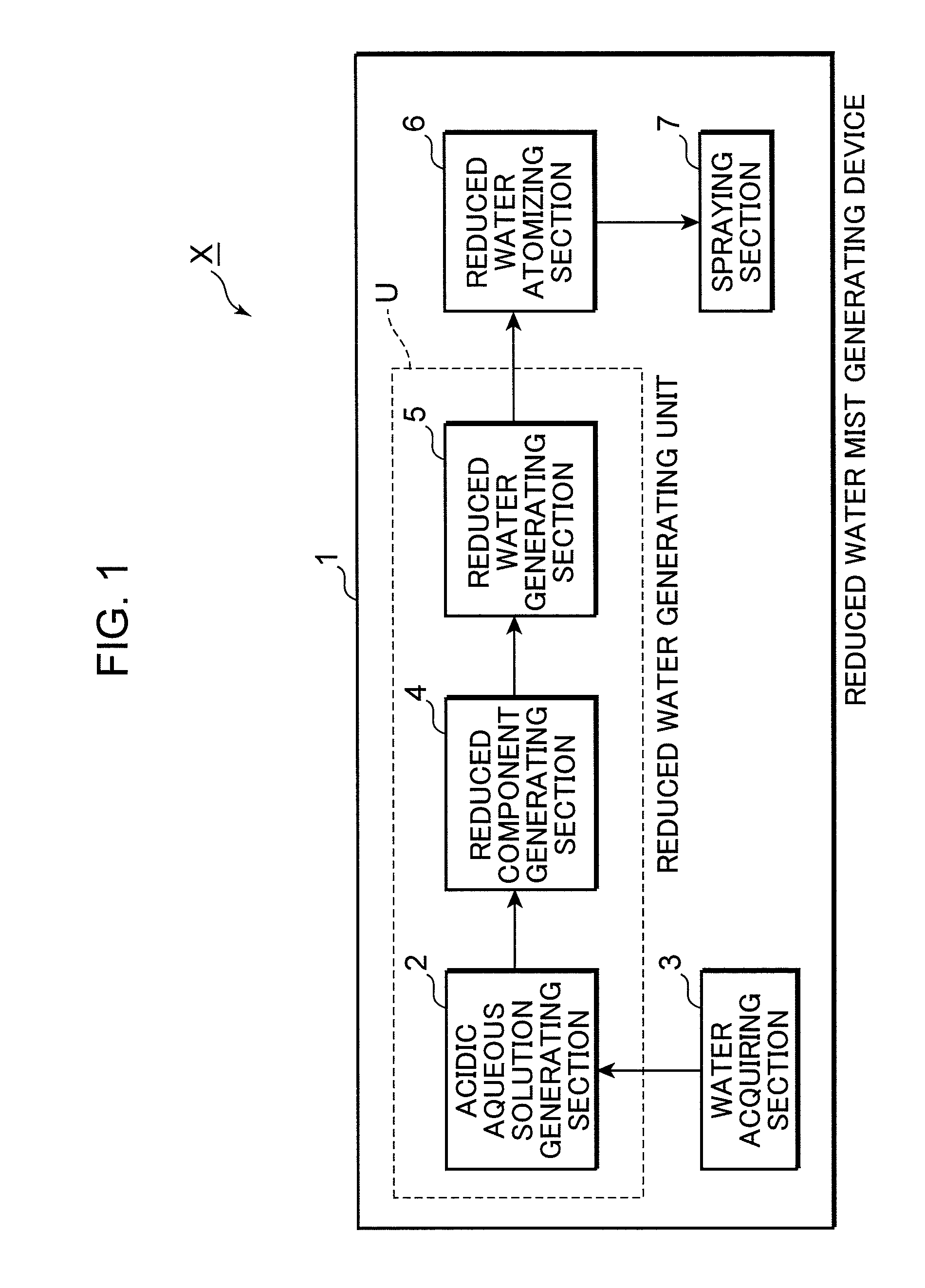
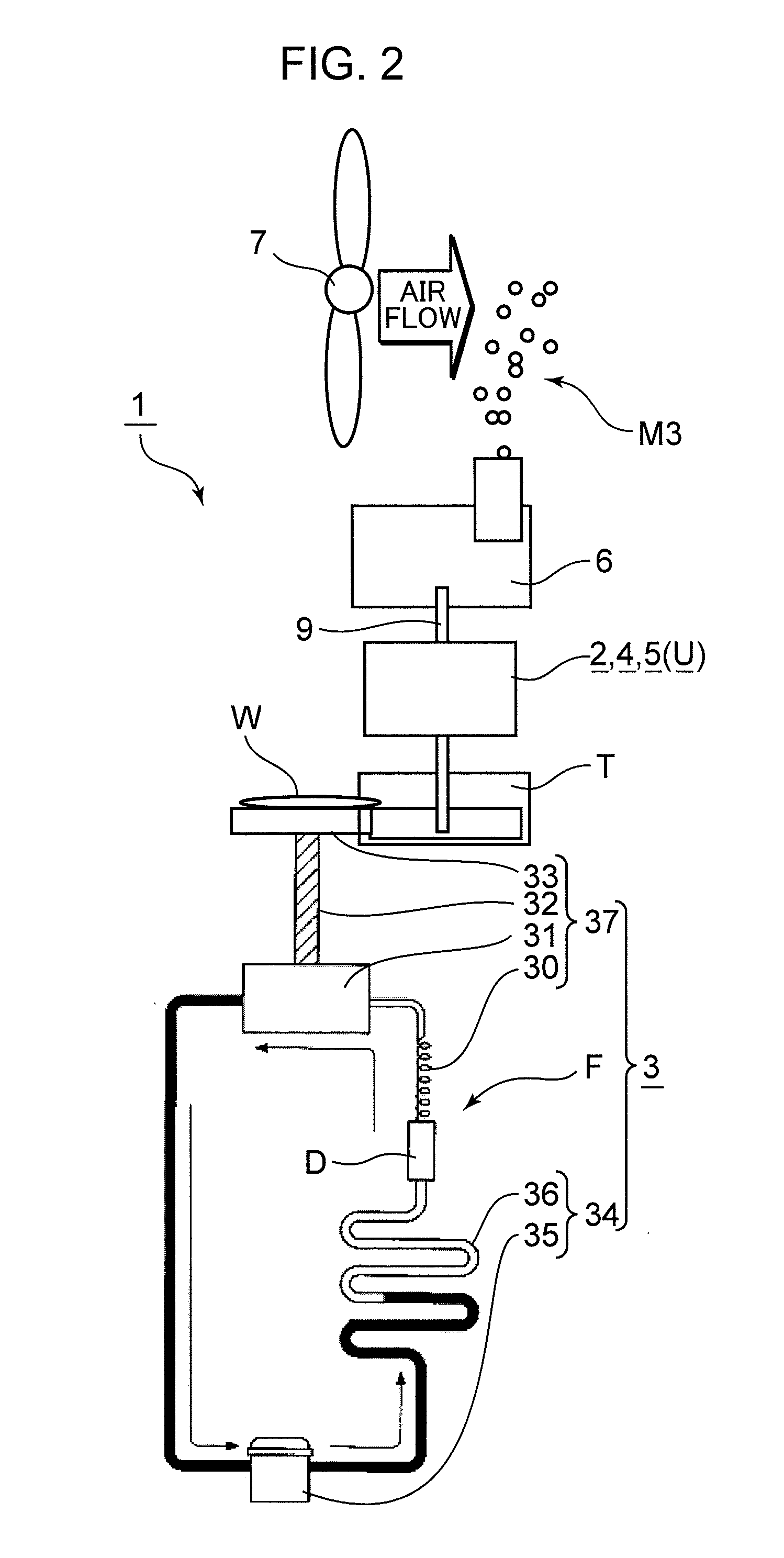
[0048]In the reduced water mist generating device 1 shown in FIG. 2, the water acquiring section 3 includes a heat radiating section 34 that compresses refrigerant gas to a high-temperature and high-pressure state and then causes heat radiation to obtain refrigerant liquid, and a cooling section 37 that depressurizes the refrigerant liquid and then evaporates the refrigerant liquid to obtain refrigerant gas. Thus, the water acquiring section 3 includes a heat exchanger having the heat radiating section 34 and the cooling section 37.
[0049]In such water acquiring section 3, the heat radiating section 34 and the cooling section 37 are provided in a refrigeration cycle section F. The heat radiating section 34 is provided with a compressor 35 that compresses the refrigerant gas to a high-temperature and high-pressure state and a condenser 36 in which the refrigerant gas at a high temperature and under a high pressure is cooled by heat radiation and refrige...
configuration example 2
Specific Configuration Example 2
[0055]In the reduced water mist generating device 1 shown in FIG. 3, the water acquiring section 3 includes a Peltier element 38 that acquires water by condensation of moisture contained in the air through cooling with a cooling surface 40.
[0056]The Peltier element 38 has the cooling surface 40 and a heat radiating surface 42. The dew condensation water generating section 33 is attached to the cooling surface 40. The cooling surface 40 and the dew condensation water generating section 33 may be thermally connected. A heat radiating fin 43 is attached to the heat radiating surface 42.
[0057]In such water acquiring section 3, when an electric current is supplied to the Peltier element 38 by a power source 41 for the Peltier element, the cooling surface 40 of the Peltier element 38 is cooled and this cooling effect reaches the dew condensation water generating section 33. As a result, the dew condensation water generating section 33 is also cooled, the ai...
configuration example 3
Specific Configuration Example 3
[0061]In the reduced water mist generating device 1 shown in FIG. 4, the water acquiring section 3 includes an adsorbent 45 that adsorbs moisture contained in the air and a heater 49 that heats the adsorbent 45 and causes desorption of the moisture adsorbed by the adsorbent 45. In this case, the preferred adsorbent 45 is a zeolite.
[0062]In such water acquiring section 3, the water tank T from a hard material such as polypropylene is provided in the lower portion inside a housing 51, and an upper opening Ta of the water tank T is closed with an adsorbing body 44.
[0063]The adsorbing body 44 is constituted by the adsorbent 45 as the main component thereof, a water-permeable hard rear plate 46 such as a mesh provided on the rear surface side of the adsorbent 45, and a moisture-permeable and water-impermeable film 47 provided on the front surface side of the adsorbent 45. The rear plate 46 is supported by a receiving section 48 provided in the upper openin...
PUM
| Property | Measurement | Unit |
|---|---|---|
| Temperature | aaaaa | aaaaa |
| Pressure | aaaaa | aaaaa |
| Acidity | aaaaa | aaaaa |
Abstract
Description
Claims
Application Information
 - R&D
- Intellectual Property
- Life Sciences
- Materials
- Tech Scout
- Unparalleled Data Quality
- Higher Quality Content
- 60% Fewer Hallucinations
Browse by: Latest US Patents, China's latest patents, Technical Efficacy Thesaurus, Application Domain, Technology Topic, Popular Technical Reports.
© 2025 PatSnap. All rights reserved.Legal|Privacy policy|Modern Slavery Act Transparency Statement|Sitemap|About US| Contact US: help@patsnap.com


