
Magnetocaloric device

a magnetic device and caloric technology, applied in the direction of refrigeration components, machine operation mode, light and heating apparatus, etc., can solve the problems of difficult extraction of additional energy savings from such technologies, significant environmental challenges, and the recycling of working fluids, so as to achieve reliable, energy-efficient, and scaleable

Inactive Publication Date: 2011-07-07
GENERAL ELECTRIC CO
View PDF19 Cites 84 Cited by
  • Summary
  • Abstract
  • Description
  • Claims
  • Application Information

AI Technical Summary

Benefits of technology

[0006]A magnetic system that is reliable, energy eff...

Problems solved by technology

Conventional refrigeration technologies suffer from several drawbacks.
Such VC refrigeration technologies typically employ chlorofluorocarbon (CFC) based gases as working fluids, or refrigerants, which CFC based working fluids pose well documented environmental challenges, for instance, recycling of the working fluids is known to present significant environment challenges.
Furthermore, refrigeration technologies based on the JT effect are mature technologies and extracting additional energy savings out of such technologies has proved difficult.
For instance, magnetic refrigeration systems do not employ CFC based gases.
Magnetic assemblies according to presently available designs however, suffer from several drawbacks.
For instance, presently available designs often utilize complex fluid transfer mechanisms via which circulates a heat exchange fluid.
Such designs often suffer from reliability issues or prohibitively high manufacturing costs.
Furthermore, many of the present generation designs are not readily scaleable.

Method used


Image

  • Magnetocaloric device
  • Magnetocaloric device
  • Magnetocaloric device

Examples


Embodiment Construction

[0018]In the following description, whenever a particular aspect or feature of an embodiment of the invention is said to comprise or consist of at least one element of a group and combinations thereof, it is understood that the aspect or feature may comprise or consist of any of the elements of the group, either individually or in combination with any of the other elements of that group.

[0019]Those of skill in the art would be aware that MC materials may be classified as positive MC materials or as negative MC materials. Positive MC materials are those which warm up when magnetized and cool down when demagnetized, while negative MC materials cool down when magnetized and warm up when demagnetized. It is stated that the discussions herein are applicable to both positive and negative MC materials. However, for the sake of brevity, the discussions herein are developed with reference to “positive” MC materials. Furthermore, it is noted that, in the discussions herein, the terms “demagne...


PUM


Abstract

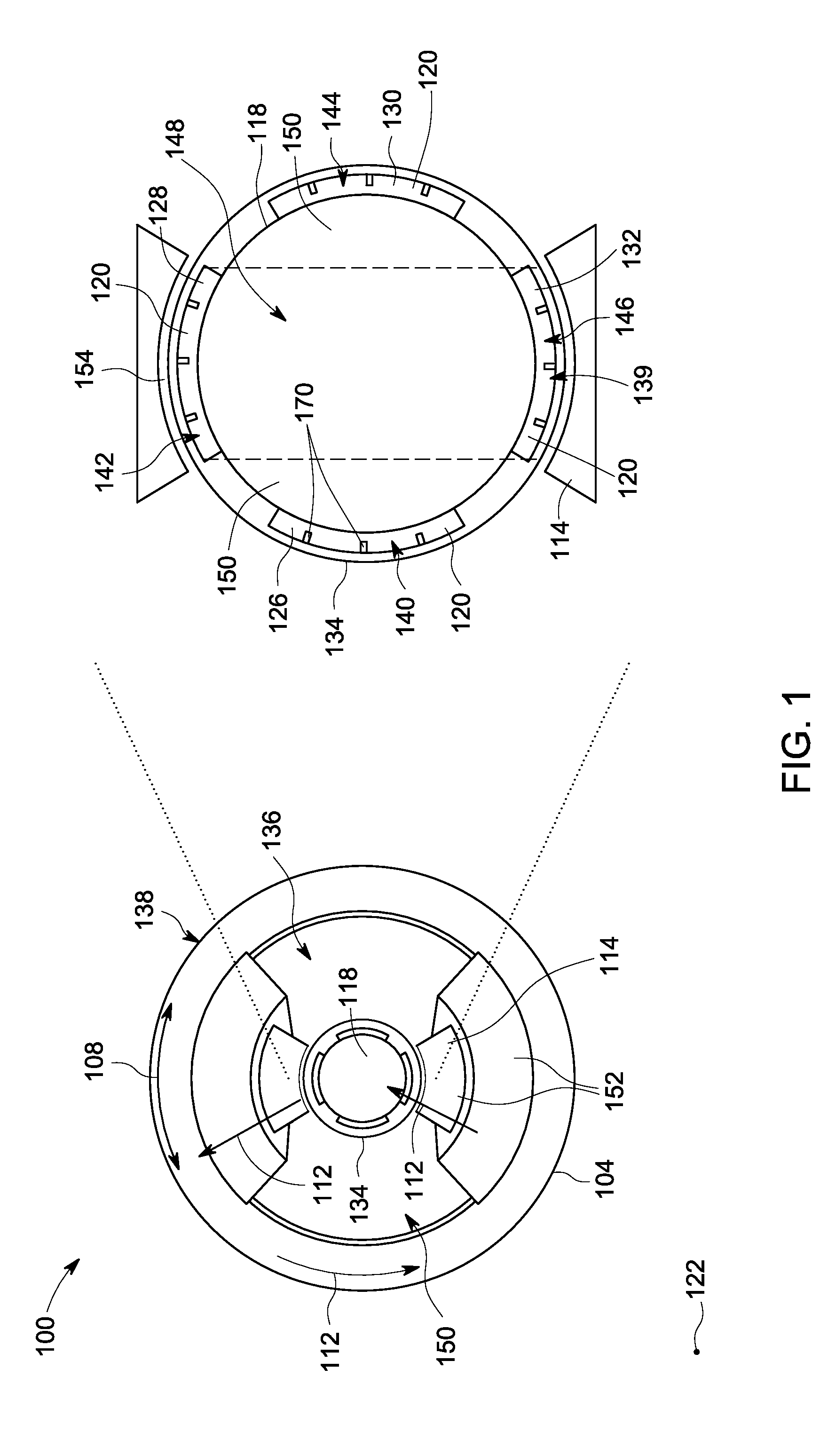
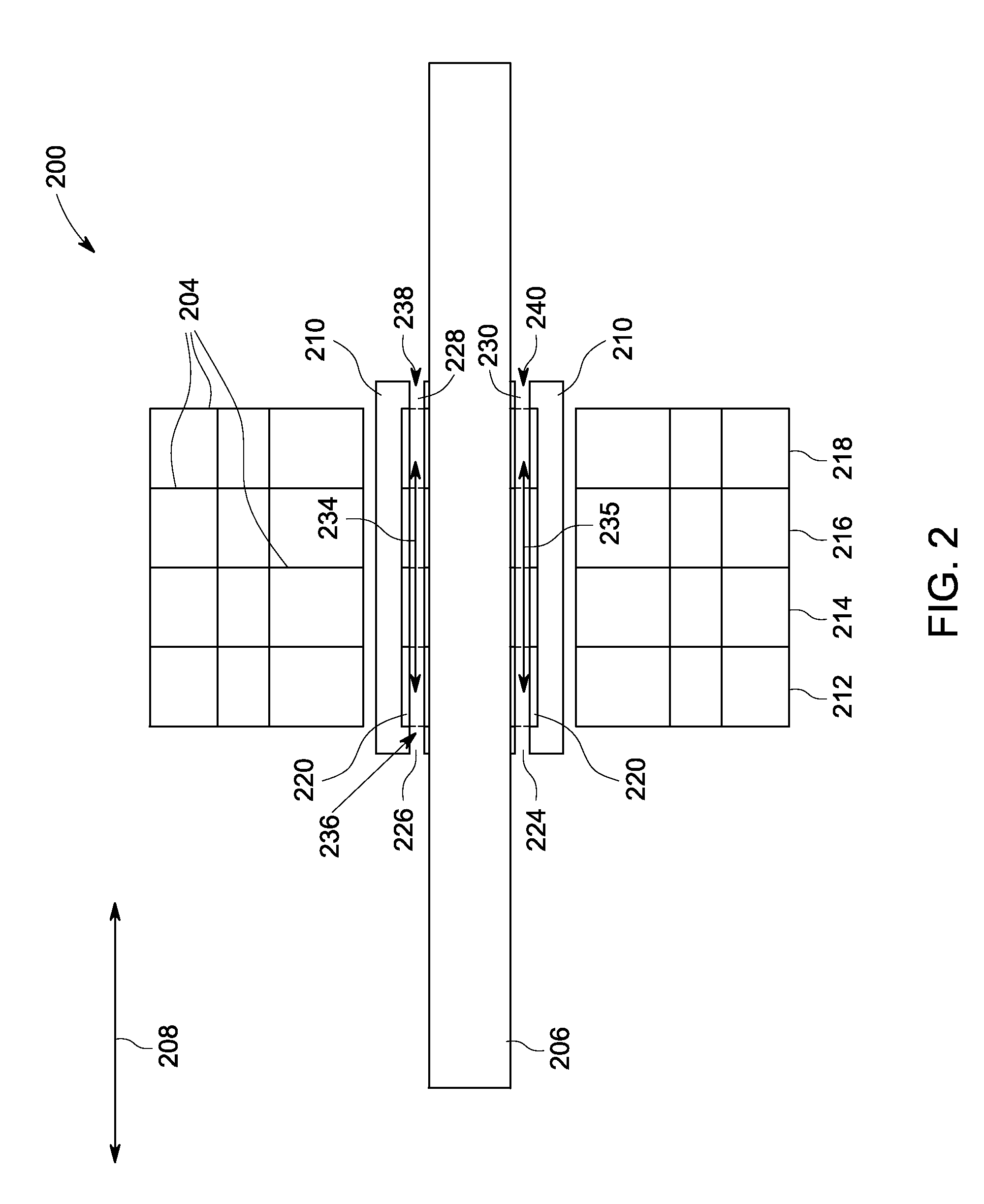
A magneto-caloric (MC) device is disclosed. The MC device comprise a rotor, a housing disposed about and concentric with the rotor and mechanically coupled to the rotor, wherein the housing comprises at least one axial slot, at least one set of MC elements, wherein each set of MC elements comprises at least one MC element, and at least one MC element of each set of MC elements is disposed within each of the at least one axial slots, and at least one working-segment corresponding to each set of MC elements, wherein each working-segment is disposed axially around the rotor and external to the housing, and wherein each working-segment comprises, a yoke substantially defining an inner volume comprising a first inner volume and a second inner volume, and a magnetic field production (MFP) unit magnetically coupled to the yoke and configured to provide a magnetic field within the first inner volume.

Description

BACKGROUND[0001]The subject matter disclosed herein generally relates to magneto-caloric (MC) devices, and refrigeration or a cooling systems based on MC devices.[0002]Conventional refrigeration technologies suffer from several drawbacks. For instance, one of the more common conventional refrigeration technologies, namely, vapor compression (VC) refrigeration, is based on exploitation of the Joule-Thomson (JT) effect, as per which effect, an adiabatic expansion or compression of a gas results in a temperature change of the gas. Such VC refrigeration technologies typically employ chlorofluorocarbon (CFC) based gases as working fluids, or refrigerants, which CFC based working fluids pose well documented environmental challenges, for instance, recycling of the working fluids is known to present significant environment challenges. Furthermore, refrigeration technologies based on the JT effect are mature technologies and extracting additional energy savings out of such technologies has p...

Claims


Application Information

Patent Timeline
IPC IPC(8): F25B21/00F25B41/00
CPCY02B30/66F25B2321/0023F25B2321/002F25B21/00Y02B30/00
Inventor BARVE, JAYESHKUMAR JAYANARAYANMENON, SHISHIR CHANDRASEKHARANBARASU, RAMASAMYSUBRAMANIAM, PRADIP RADHAKRISHNANKUMAR, VIJAYREDDY, SUDHAKAR EDDULAHANUMANTHA, RAVIKUMAR
Owner GENERAL ELECTRIC CO
Learn More