Eureka AIR delivers breakthrough ideas for toughest innovation challenges, trusted by R&D personnel around the world.

Method of correcting brightness of electronic display

a technology of electronic display and brightness correction, applied in the field of brightness correction method of electronic display, can solve problems such as errors and inaccuracy, non-uniformity, exhausting correction engineers, etc., and achieve the effect of improving the speed of brightness correction of electronic display

Inactive Publication Date: 2011-06-30
ZHONGQING DIGITAL EQUIP
View PDF7 Cites 12 Cited by
  • Summary
  • Abstract
  • Description
  • Claims
  • Application Information

AI Technical Summary

Benefits of technology

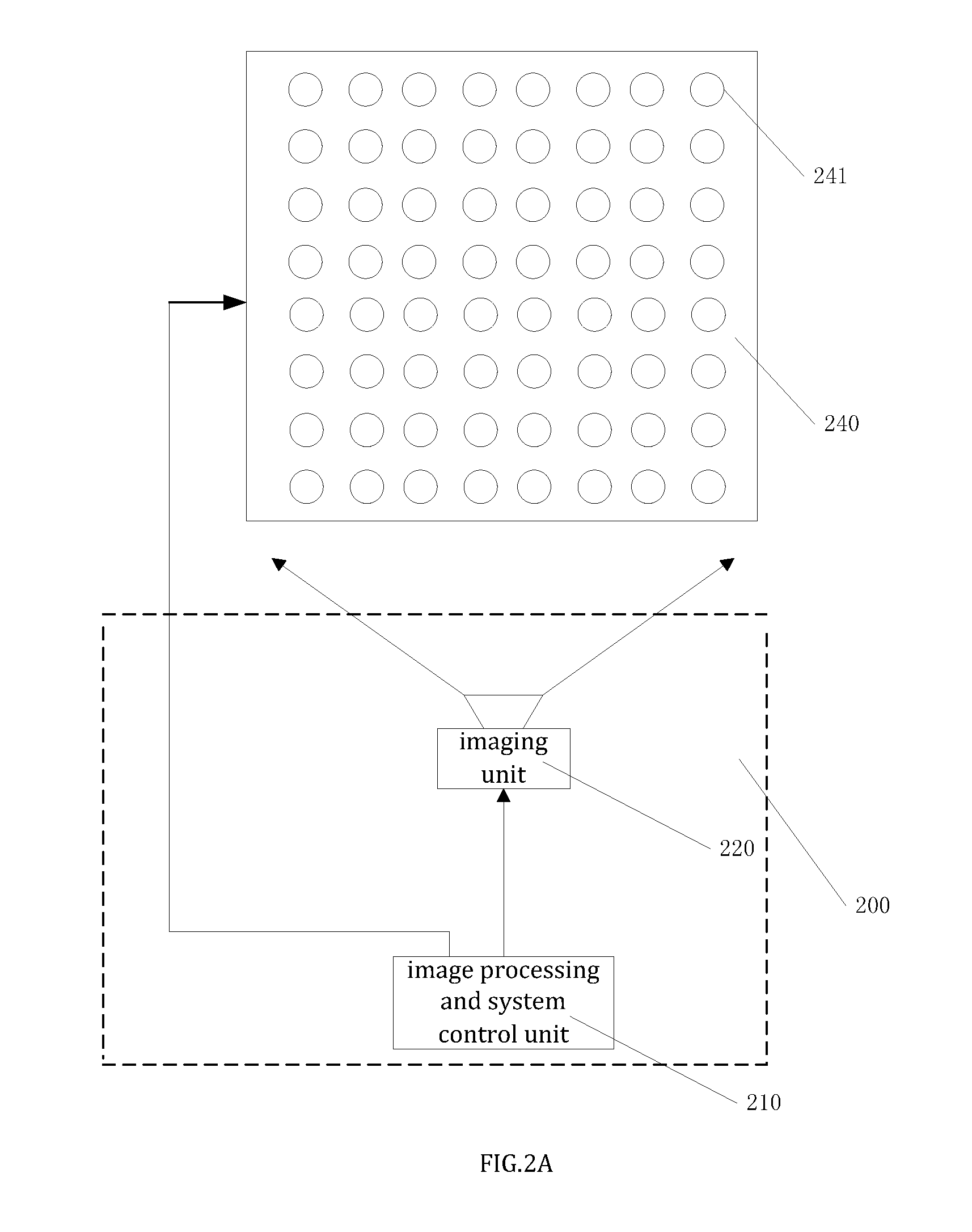
[0077]Compared with the prior art, the present invention provide a method and system of the brightness correction for an electronic display. We could get the characteristic values of several light-emitting components on the screen by taking a photograph of the display. Furthermore, we could get the actual brightness of several light-emitting components with the characteristic values stated above, and finish the brightness correction. This method reduces the time cost of surveying the brightness of light-emitting components and improves the efficiency of the correction for the brightness nonuniformity.

Problems solved by technology

However, the nonuniformity comes up only after a period of usage.
This solution exhausts correction engineers, brings errors and inaccuracies into the results, for which the nice correction effects usually could not be achieved.As stated above, in the prior art condition, the brightness correction of electronic display is performed by the way of spot-spot examination and correction on light-emitting components of the display.
For a display with millions of light-emitting components, it will take dozens of hours to finish the correction if the examination of 10 pixels costs 1 second, therefore the whole process will take too much time and human resources.After all, the prior art that has apparent disadvantages needs to be improved.

Method used


Image

  • Method of correcting brightness of electronic display
  • Method of correcting brightness of electronic display
  • Method of correcting brightness of electronic display

Examples


Embodiment Construction

[0084]Make a further description for the preferred embodiments of the invention with the figures.

Mode 1:

[0085]The method of correcting brightness of an electronic display stated above is to capture an imaging picture of the display by photographing, which contains steps as follows:

[0086]Step A: Fix the photographic distance between display and imaging units; fix the photographic brightness of the electronic display; focus on the imaging units; fix the photographic parameters of the imaging units. The steps do not need to be implemented in a particular order, and could be implemented repeatedly or at the same time.

[0087]Step B: Fix the locations of each light-emitting component at the imaging photo; fix the imaging region of each light-emitting component at the imaging photo; get the grey value of each pixel in the imaging region of each light-emitting component, and calculate the characteristic values of each light-emitting component imaging.

[0088]Step C: Calculate the actual bright...


PUM


Abstract

The present invention discloses a method of brightness correction for the electronic display, which consists of the following steps: take pictures of the electronic display; get the characteristic values of all the light-emitting components in the pictures; calculate the correction values of each light-emitting component with the characteristic values; correct the brightness of the display with the correction values. The present invention reduces the time cost of measuring the actual brightness values of the light-emitting components, and improves the efficiency of correcting the brightness uniformity of the electronic display.

Description

FIELD OF THE INVENTION[0001]The present invention relates to a correction method in the display field, and more particularly to a brightness correction method of the electronic display.BACKGROUND OF THE INVENTION[0002]The brightness nonuniformity of each pixel in an electronic display would seriously affect the quality of display. Monochrome display, for instance, the brightness nonuniformity of each pixel is reflected in the brightness discontinuity of the display. For a color display, the brightness nonuniformity is not only reflected in the discontinuity of the display, but also in the chromatic aberration.[0003]In the prior art condition, because of the limit of the production technology, there are differences among the characteristic parameters of the light-emitting components which constitute a display. One pixel is consisted of one or more light-emitting components with characteristic parameter differences, which means the existence of the characteristic parameter differences...

Claims


Application Information

Patent Timeline
IPC IPC(8): G09G5/00
CPCG09G3/006G09G2320/0233G09G3/20
Inventor SHAO, YIN-LIANGYANG, LEIGUAN, LI
Owner ZHONGQING DIGITAL EQUIP
Why Eureka
Eureka Blog
Learn More