
Tortuous path static mixers and fluid systems including the same

Inactive Publication Date: 2011-06-23
3M INNOVATIVE PROPERTIES CO
View PDF9 Cites 15 Cited by
  • Summary
  • Abstract
  • Description
  • Claims
  • Application Information

AI Technical Summary

Benefits of technology

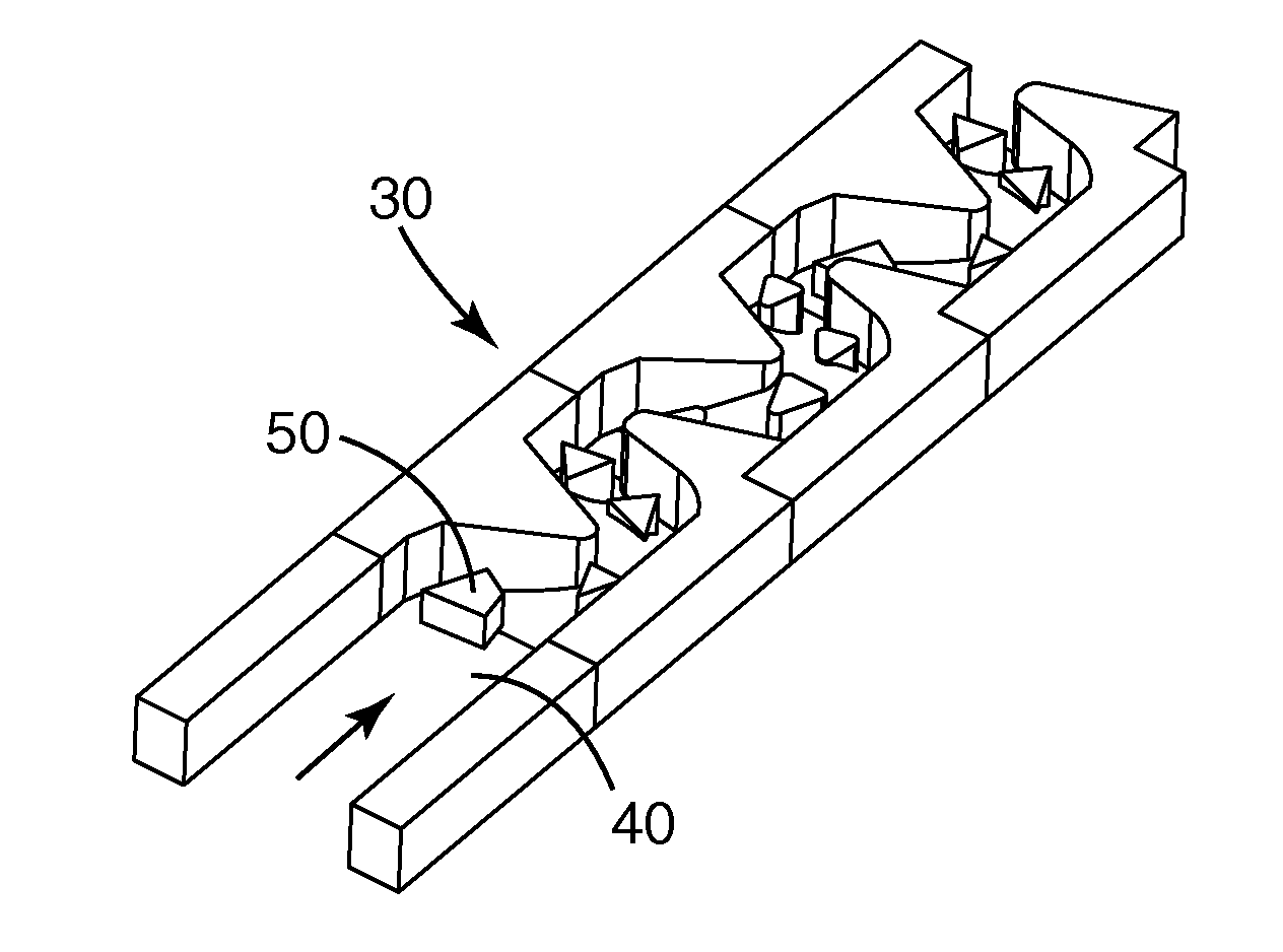
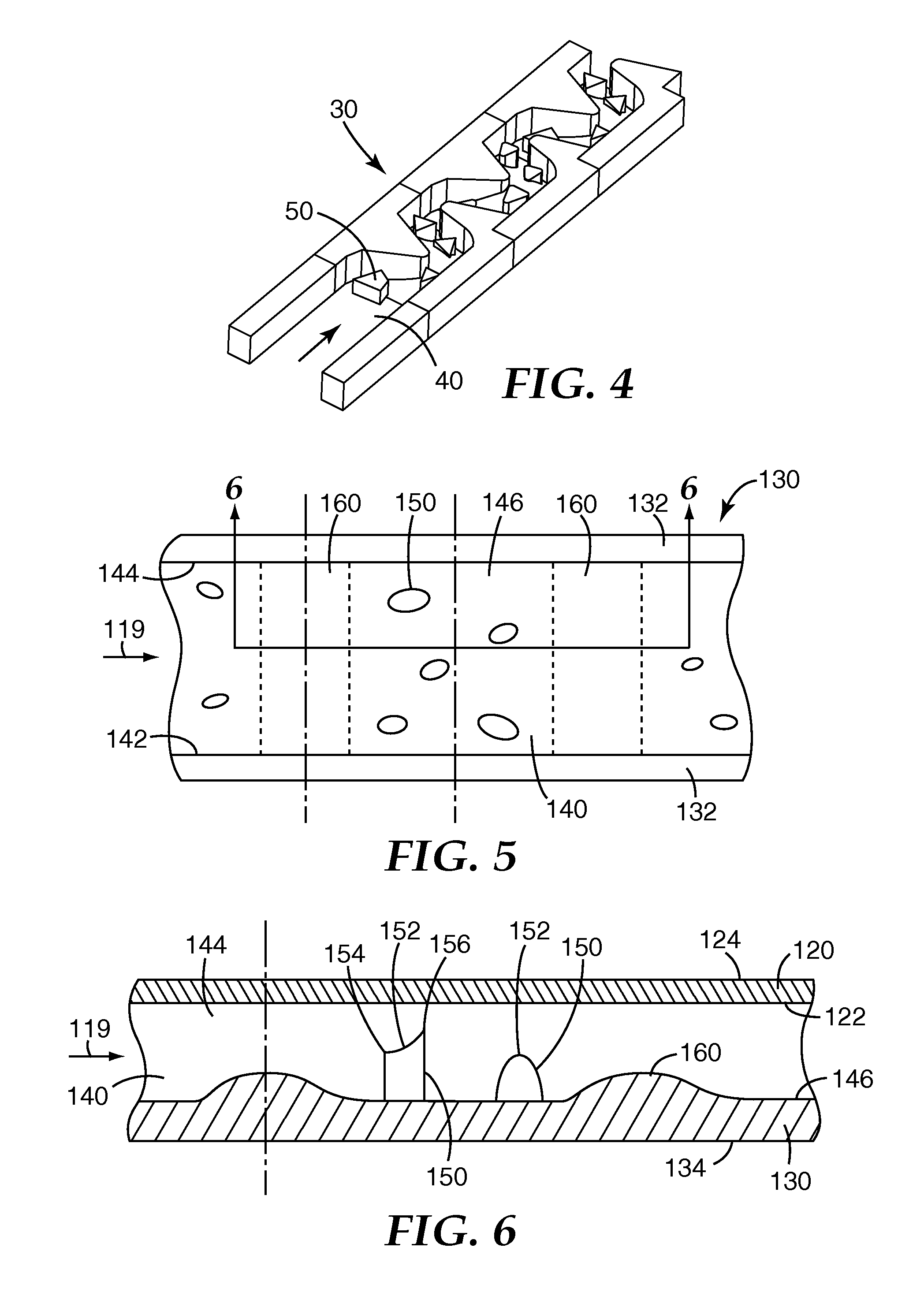
[0003]The present invention provides static mixers and fluid systems incorporating one or more of the static mixers. The static mixers preferably include one or more channels that provide a tortuous path through a body, wherein fluid flowing through each channel defines a downstream direction through the tortuous path created within the channel. The tortuous path of the channel is preferably formed by a set of flow obstacles protruding into the channel and a set of flow restrictions positioned along the channel between the inlet and the outlet. Each flow restriction has a downstream length over which the open cross-sectional area of the channel decreases and then increases when moving in the downstream direction. The flow obstacles preferably cause fluids flowing through the channel to change direction while the flow restrictions cause the fluid to accelerate and decelerate as it flows past the flow restrictions. The changes in fluid direction and velocity preferably provide a tortuous path that enhances mixing of fluids passing through the channel in the downstream direction.
[0006]One potential advantage of the mixers of the present invention may include, e.g., a reduction in non-specific binding of analytes to the mixing structures which may be beneficial in connection with biological materials passed through the mixers. In part, the non-specific binding may be reduced by the small surface area to which the biological materials are exposed.
[0007]Another potential advantage of the mixers of the present invention is an ability to process smaller sample volumes because of a reduction in the amount of dead volume in the mixers of the present invention.
[0008]In some embodiments, static mixers of the present invention may be provided in the form of a multilayer structure that can be manufactured by assembling a base in which the bottom surface of the channel and the set of flow obstacles are formed. The base may also preferably include structure defining the edges of the channel. As a result, the top surface of the channel may preferably be formed by a flat, featureless cover attached to the base over the channel features that are formed in the base. Providing all of the features in base, with the top surface formed by a flat, featureless cover may provide a convenient and economical static mixer structure, particularly where the base may be formed by any suitable process, e.g., molding, etching, sintering, etc.

Problems solved by technology

In many instances, however, the mixers suffer from issues such as relatively high pressure drop, limited flow rates, inefficient mixing, etc.

Method used


Image

  • Tortuous path static mixers and fluid systems including the same
  • Tortuous path static mixers and fluid systems including the same
  • Tortuous path static mixers and fluid systems including the same

Examples


Embodiment Construction

[0032]In the following detailed description of illustrative embodiments of the invention, reference is made to the accompanying figures of the drawing which form a part hereof, and in which are shown, by way of illustration, specific embodiments in which the invention may be practiced. It is to be understood that other embodiments may be utilized and structural changes may be made without departing from the scope of the present invention.

[0033]A mixer body 10 containing one exemplary static mixer is depicted in the perspective view of FIG. 1. As depicted in FIG. 1, the body 10 may preferably be in the form of a multilayer structure including two or more layers that provide a cover 20 and a base 30.

[0034]The mixer body 10 preferably includes one or more inlets, with the depicted body 10 including a first inlet 12 and a second inlet 14, both of which preferably open into the static mixer located in the body 10. The static mixer in body 10 also preferably includes one or more outlets t...


PUM


Abstract

Static mixers and fluid systems incorporating one or more of the static mixers. The static mixers may include one or more channels that provide a tortuous path through a body, wherein fluid flowing through each channel defines a downstream direction through the tortuous path created within the channel. The tortuous path of the channel is preferably formed by a set of flow obstacles protruding into the channel and a set of flow restrictions positioned along the channel between the inlet and the outlet. Each flow restriction has a downstream length over which the open cross-sectional area of the channel decreases and then increases when moving in the downstream direction.

Description

CROSS REFERENCE TO RELATED APPLICATIONS[0001]This application claims the benefit of U.S. Provisional Patent Application No. 61 / 081,847, filed Jul. 18, 2008, which is incorporated herein by reference.[0002]Efficient and thorough mixing of materials is a need that is addressed by many different static and dynamic mixers, although many conventional mixers used to mix small volumes of materials often rely on electrical or magnetic fields, long micro-channels or generation of alternating adjacent fluid layers with thicknesses in the micrometer (μm) range (e.g., 25-40 μm) (where the fluid layers are redirected such that they mix). In many instances, however, the mixers suffer from issues such as relatively high pressure drop, limited flow rates, inefficient mixing, etc.SUMMARY OF THE INVENTION[0003]The present invention provides static mixers and fluid systems incorporating one or more of the static mixers. The static mixers preferably include one or more channels that provide a tortuous ...

Claims


Application Information

Patent Timeline
IPC IPC(8): B01F5/06G01N33/00
CPCB01F5/061B01F5/0646B01F2005/0636B01F13/0059B01F2005/0621B01F5/0647B01F25/431B01F25/4317B01F25/431971B01F25/4331B01F25/433B01F33/30
Inventor CASTRO, GUSTAVO H.COBIAN, PAUL J.
Owner 3M INNOVATIVE PROPERTIES CO
Learn More