Eureka AIR delivers breakthrough ideas for toughest innovation challenges, trusted by R&D personnel around the world.

Image processing apparatus, processing method therefor, and non-transitory computer-readable storage medium

a processing method and image processing technology, applied in the field of image processing apparatus, can solve the problems of becoming more difficult to manually associate these line segments, and the difficulty of this technique in accurately performing the association

Active Publication Date: 2011-06-23
CANON KK
View PDF3 Cites 16 Cited by
  • Summary
  • Abstract
  • Description
  • Claims
  • Application Information

AI Technical Summary

Benefits of technology

[0011]The present invention provides a technique which can precisely associate line segments in images with each other even if similar line segments are present in the images or line segments are densely populated in the images.

Problems solved by technology

In contrast, as the number of line segments increases, it becomes more difficult to manually associate these line segments.
Considering, for example, image noise and a change in illumination, it is difficult for this technique to accurately perform the association.

Method used


Image

  • Image processing apparatus, processing method therefor, and non-transitory computer-readable storage medium
  • Image processing apparatus, processing method therefor, and non-transitory computer-readable storage medium
  • Image processing apparatus, processing method therefor, and non-transitory computer-readable storage medium

Examples


first embodiment

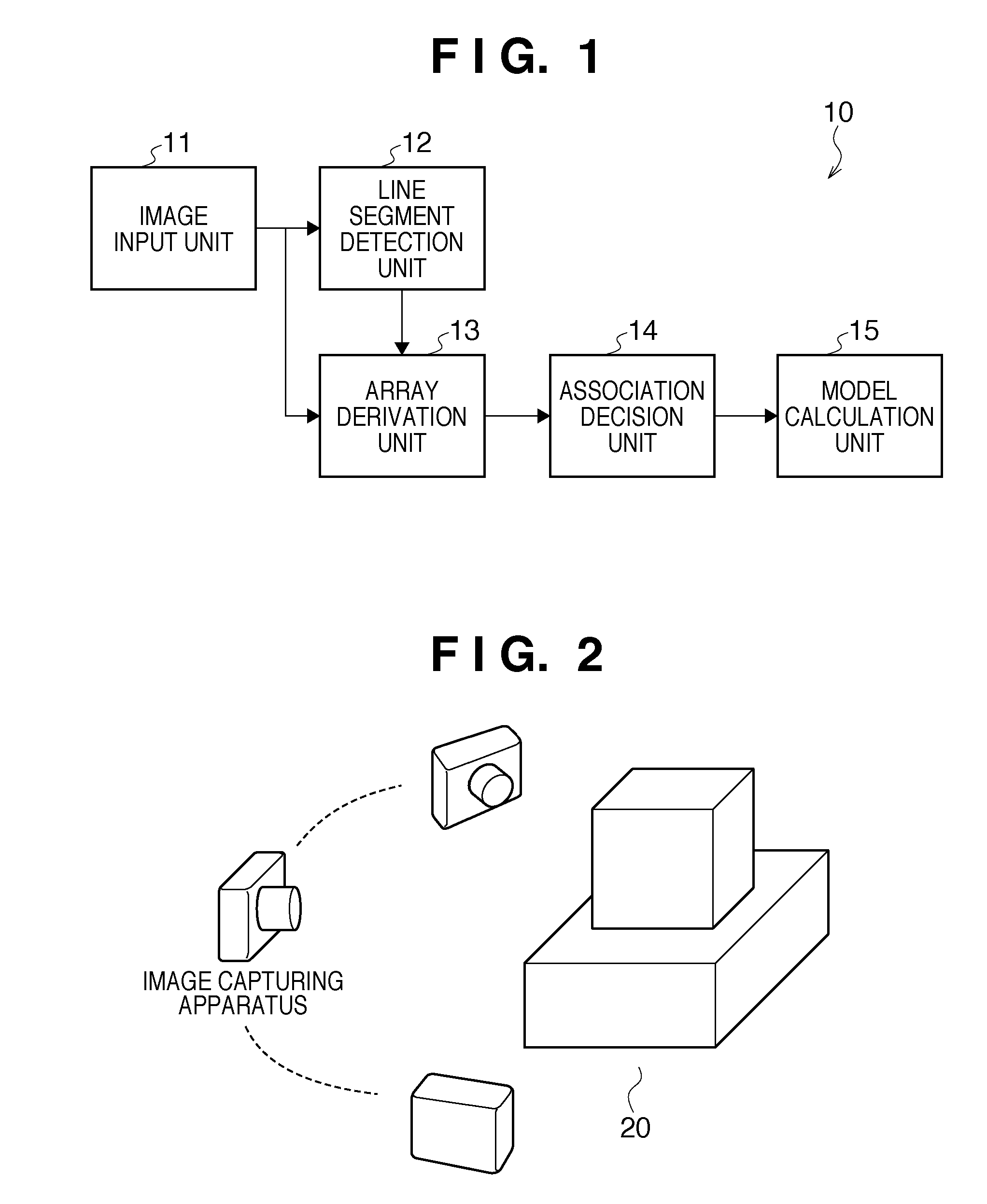
[0027]FIG. 1 is a block diagram showing an example of the functional configuration of an image processing apparatus according to an embodiment of the present invention.

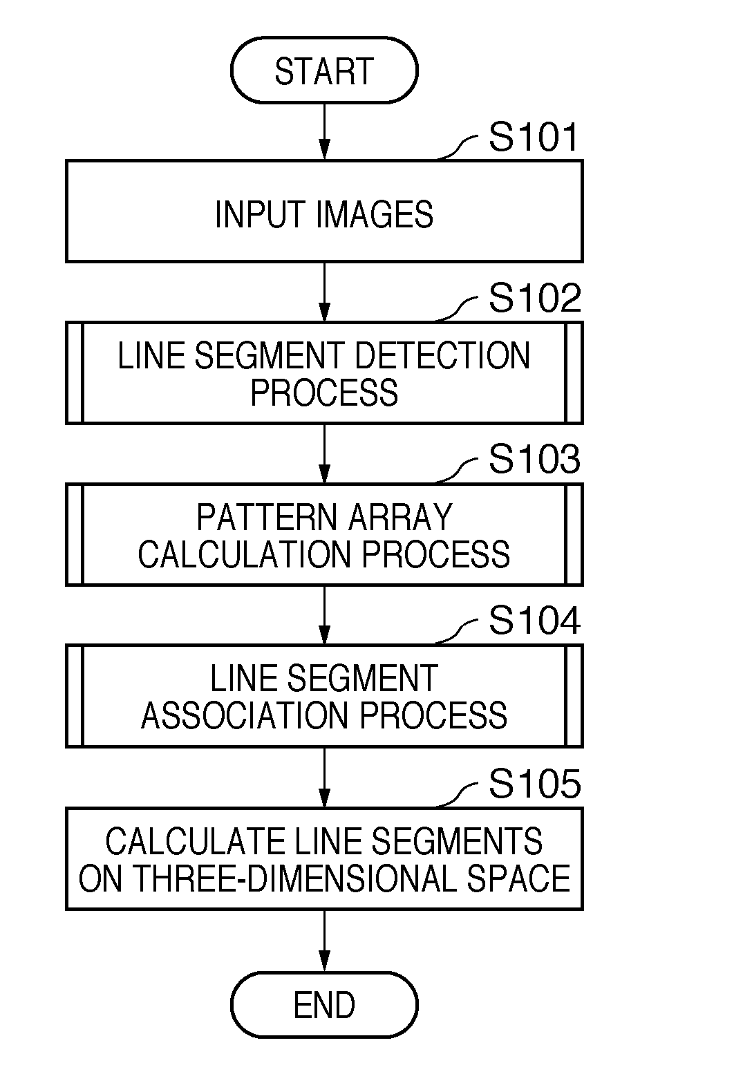
[0028]An image processing apparatus 10 generates a three-dimensional geometric model which represents a physical object by a set of line segments, using a plurality of images obtained by capturing the physical object. The image processing apparatus 10 is configured using a computer. The computer includes, for example, a main control means such as a CPU, and storage means such as a ROM (Read Only Memory) and a RAM (Random Access Memory). The computer may also include a communication means such as a network card or infrared rays, and an input / output means such as a display or a touch panel. Note that these constituent means are connected to each other via a bus, and controlled by executing programs stored in the storage means by the main control means.

[0029]The image processing apparatus 10 includes an image input unit ...

second embodiment

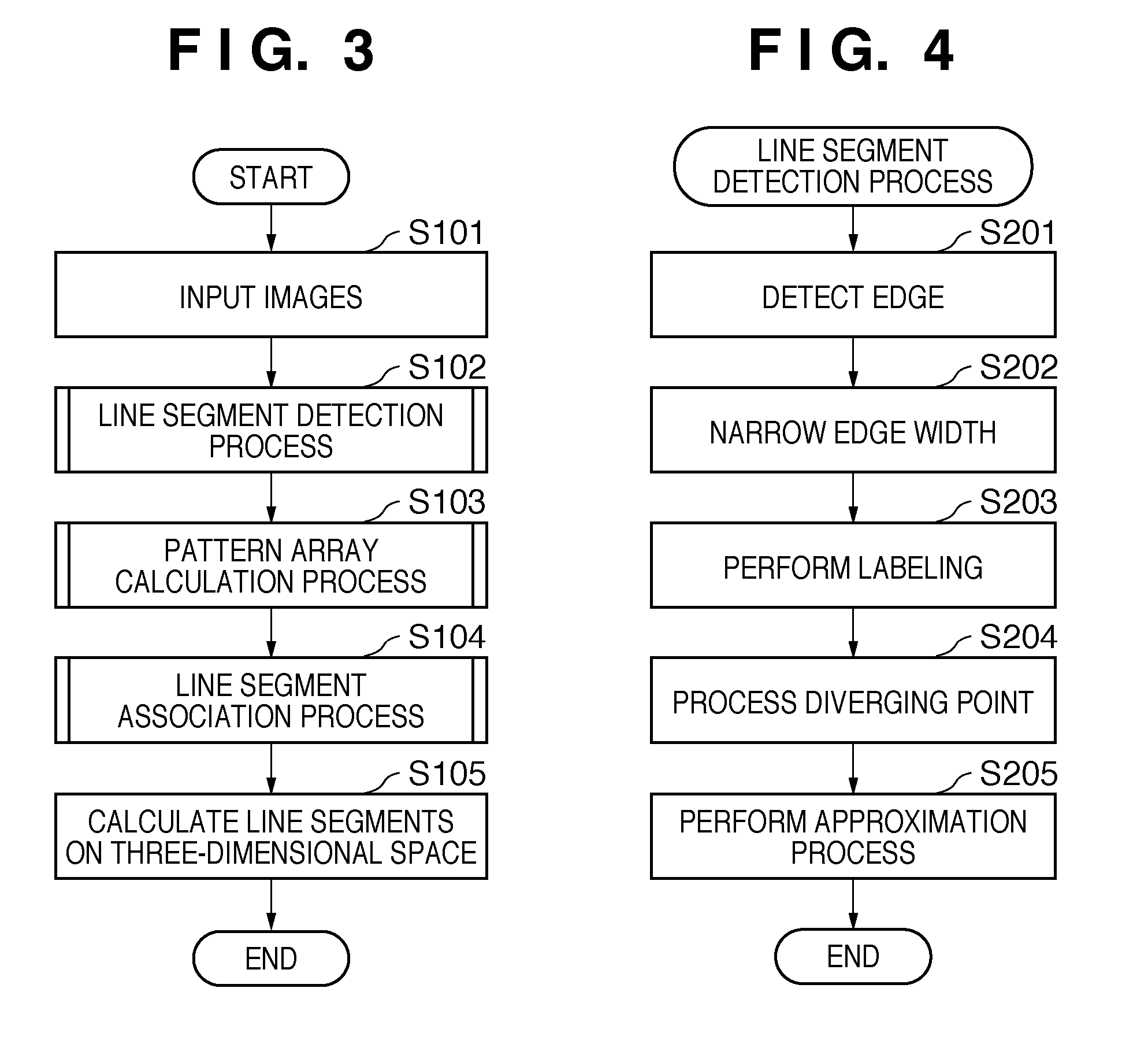
[0069]The second embodiment in which the processing time is prioritized will be described next. More specifically, in the second embodiment, pattern arrays held for respective dividing points are integrated into one pattern array, and the integrated pattern arrays of respective line segments are compared with each other (that is, each line segment has one pattern array). Note that the configuration and overall operation of an image processing apparatus 10 according to the second embodiment are the same as in FIGS. 1 and 3 referred to in the description of the first embodiment, and a description thereof will not be given. Importance will be attached to a difference from the first embodiment herein. A difference lies in a line segment association process in step S104 of FIG. 3.

[0070]A process of associating line segments in images with each other according to the second embodiment will be described herein with reference to FIG. 9. A case in which line segments in two images (a first i...


PUM


Abstract

An image processing apparatus comprising: an input unit configured to input a plurality of images obtained by capturing a target object from different viewpoints; a detection unit configured to detect a plurality of line segments from each of the plurality of input images; a setting unit configured to set, for each of the plurality of detected line segments, a reference line which intersects with the line segment; an array derivation unit configured to obtain a pattern array in which a plurality of pixel value change patterns on the set reference line are aligned; and a decision unit configured to decide association of the detected line segments between the plurality of images by comparing the pixel value change patterns, contained in the obtained pattern array, between the plurality of images.

Description

BACKGROUND OF THE INVENTION[0001]1. Field of the Invention[0002]The present invention relates to an image processing apparatus, a processing method therefor, and a non-transitory computer-readable storage medium.[0003]2. Description of the Related Art[0004]In recent years, for practical applications to mixed reality and automatic traveling of robots, techniques that measure the position and orientation of a camera relative to a physical object based on a three-dimensional geometric model of the physical object are being studied. Among others, techniques that represent a three-dimensional geometric model as a set of line segments, and measure the position and orientation of a camera so as to fit projected images of the line segments to edges in an image captured by the camera are under extensive study (for example, T. Drummond and R. Cipolla, “Real-time visual tracking of complex structures,” IEEE Transactions on Pattern Recognition and Machine Intelligence, vol. 24, no. 7, pp. 932-9...

Claims


Application Information

Patent Timeline
IPC IPC(8): G06K9/00G06V10/44
CPCG06T7/0065G06K9/4604G06T7/55G06V10/44
Inventor KOTAKE, DAISUKE
Owner CANON KK
Why Eureka
Eureka Blog
Learn More