Telephone number mapping

a technology of telephone number and mapping, applied in the field of telephone number mapping, can solve the problems of increasing the complexity of routing calls through networks, consuming a significant amount of network resources, and adding to the complexity of call processing and signaling

Active Publication Date: 2011-06-23
VERIZON PATENT & LICENSING INC
View PDF3 Cites 13 Cited by
  • Summary
  • Abstract
  • Description
  • Claims
  • Application Information

AI Technical Summary

Problems solved by technology

Routing calls through networks has become increasingly complex.
Such lookups and routing decisions typically consume a significant amount of network resources.
This different handling often adds to the complexity of call processing and signaling.

Method used


Image

  • Telephone number mapping
  • Telephone number mapping
  • Telephone number mapping

Examples


Embodiment Construction

The following detailed description refers to the accompanying drawings. The same reference numbers in different drawings may identify the same or similar elements. Also, the following detailed description does not limit the invention.

Implementations described herein relate to telephone number mapping used to identify an appropriate network element to handle a call. In one implementation, if a call originates from outside a service provider's network, a query to a telephone number mapping system may identify a call session control function element to which the call will be forwarded, as well as a border control function element to process the call prior to forwarding the call to the call session control function element. The border control function element may perform security-related processing for the outside call prior to forwarding the call.

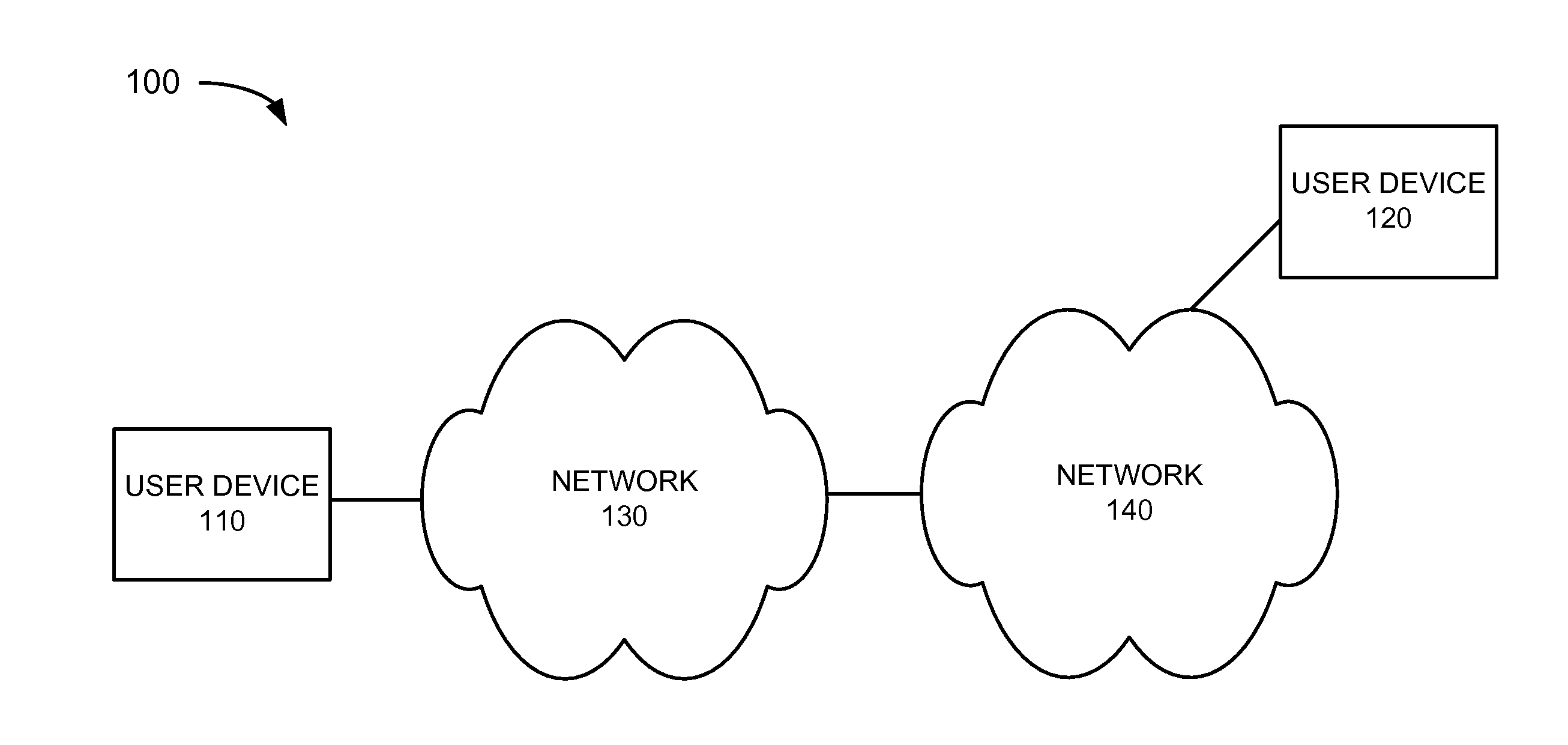
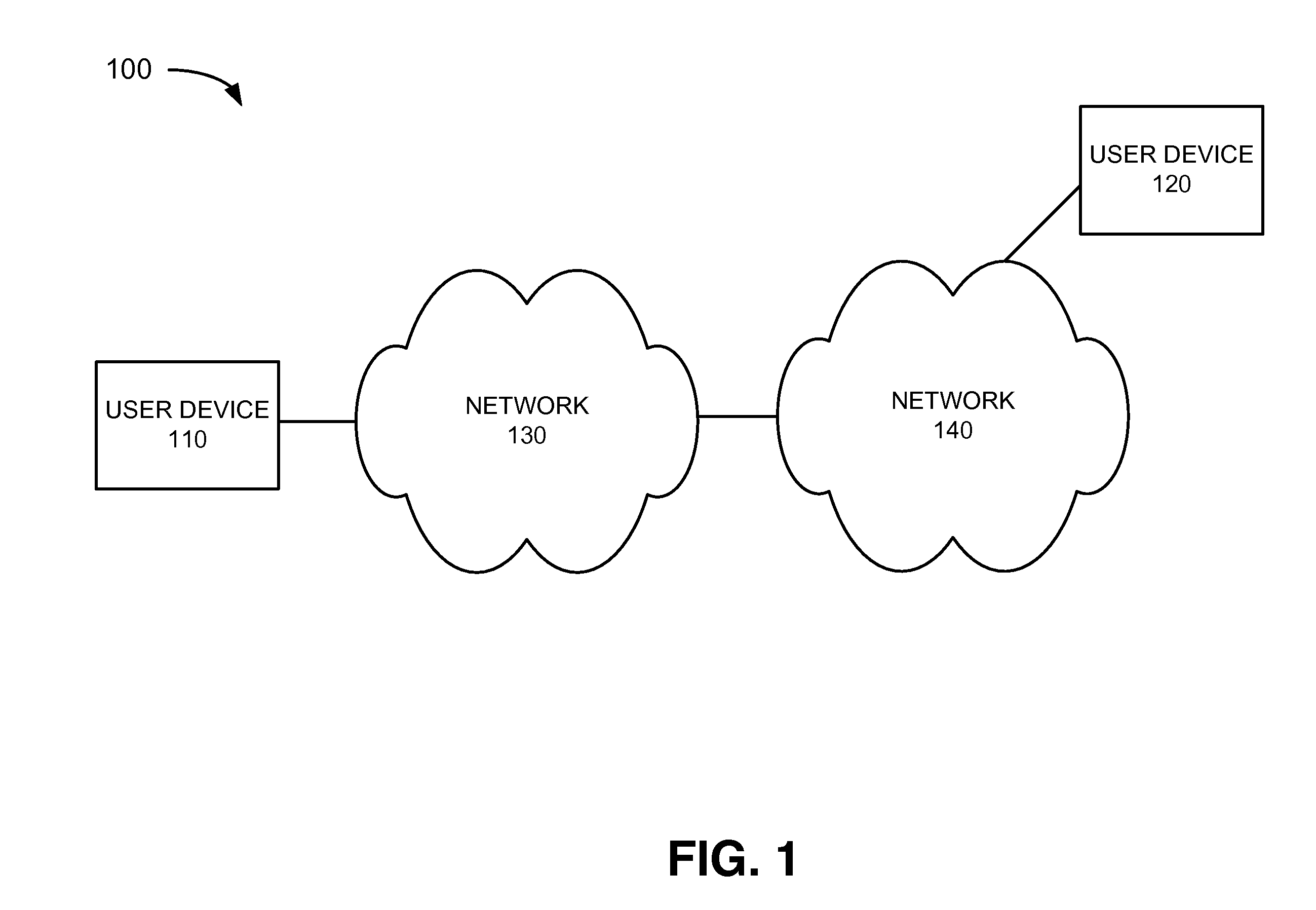
FIG. 1 is a block diagram of an exemplary network 100 in which systems and methods described herein may be implemented. Network 100 may inclu...


PUM


Abstract

A method may include receiving a telephone number mapping query associated with a call from a calling party to a called party. The method may also include identifying, based on the query, first routing information that identifies a call session control component to process the call, and second routing information that identifies a border control component. The method may further include forwarding the first routing information to the querying device, and forwarding the second routing information to the querying device when the query originated from outside a network servicing the called party.

Description

BACKGROUND INFORMATION Routing calls through networks has become increasingly complex. For example, service providers must perform a number of lookups and make routing decisions based on results of the lookups. Such lookups and routing decisions typically consume a significant amount of network resources. In addition, processing calls originating from the home network of the called party and processing calls originating from an external network may require different handling. This different handling often adds to the complexity of call processing and signaling.BRIEF DESCRIPTION OF THE DRAWINGS FIG. 1 illustrates an exemplary network in which systems and methods described herein may be implemented;FIG. 2 illustrates exemplary components included in the network of FIG. 1;FIG. 3 illustrates an exemplary configuration of one or more of the components of FIG. 2;FIG. 4 illustrates an exemplary configuration of logic components implemented in the device of FIG. 3; andFIG. 5 is a flow diagr...

Claims


Application Information

Patent Timeline
Patent Type & Authority Applications(United States)
IPC IPC(8): H04M15/06H04M7/00
CPCH04L29/1216H04L61/157H04M7/006H04M15/63H04M15/06H04M15/43H04M15/00H04L61/4557
Inventor DWIGHT, TIMOTHY M.LAU, PRISCILLASCHNEELOCH, PAUL
Owner VERIZON PATENT & LICENSING INC
Why Eureka
Try Eureka