Motor
a motor and motor technology, applied in the direction of windings, magnetic circuit rotating parts, magnetic circuit shape/form/construction, etc., can solve the problems of likely magnetic imbalance of the rotor and degrade the rotational performance, and achieve the effect of increasing the output power and keeping the number of magnets in the rotor low
- Summary
- Abstract
- Description
- Claims
- Application Information
AI Technical Summary
Benefits of technology
Problems solved by technology
Method used
Image

Examples
first embodiment
[0058]the present invention will now be described with reference to the drawings.
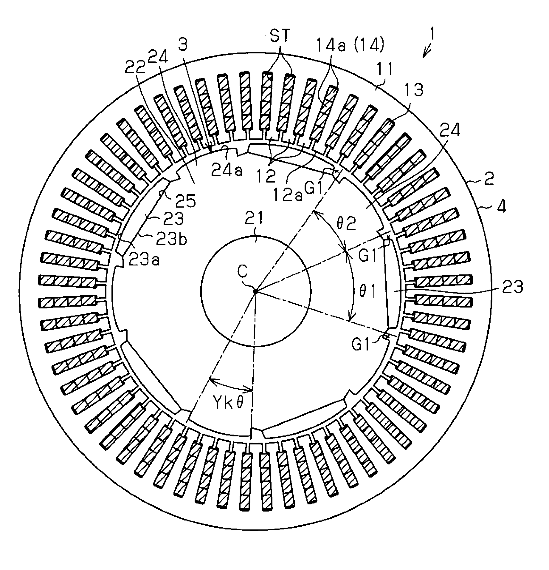
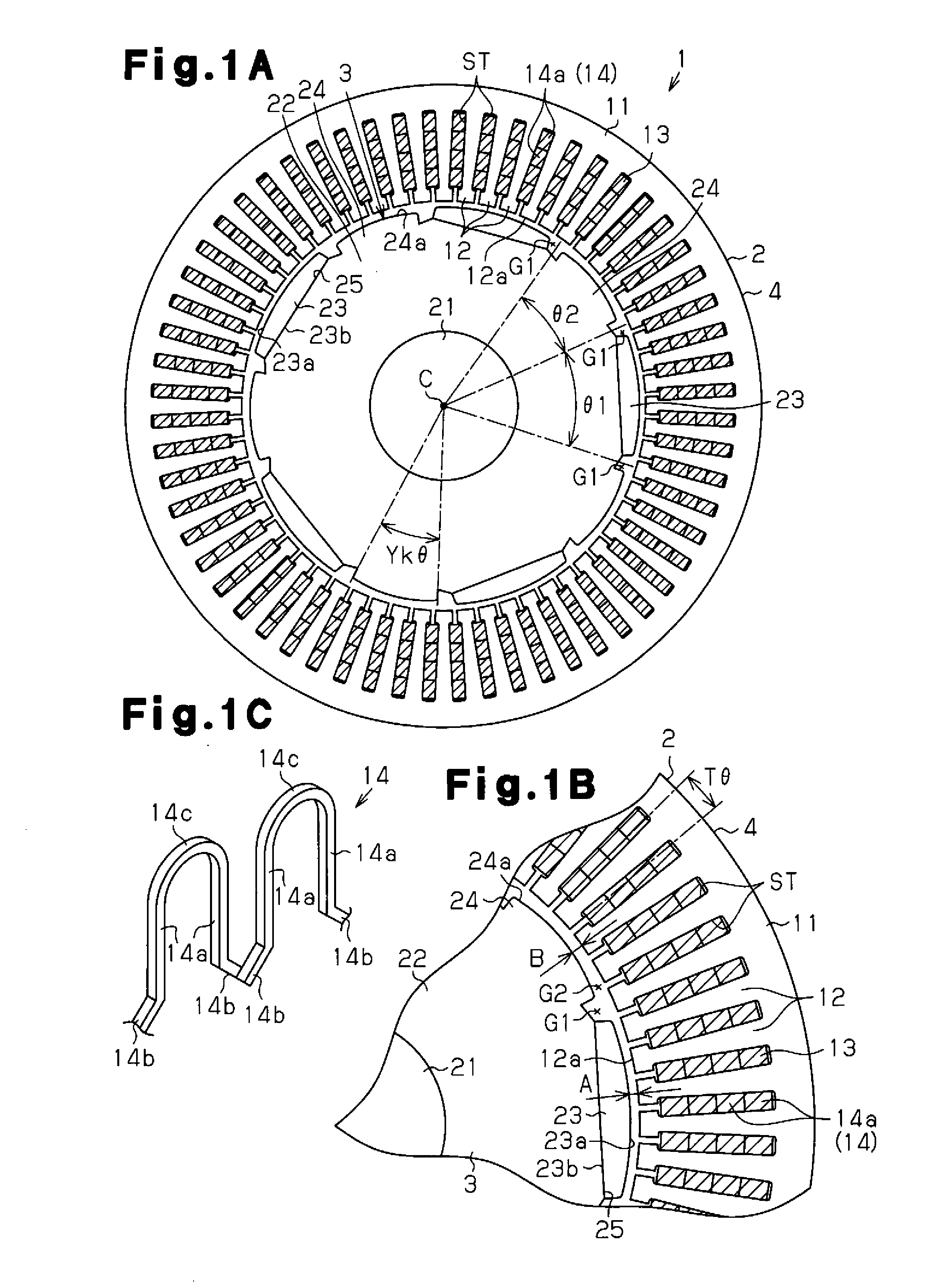
[0059]As shown in FIG. 1A, an inner rotor type motor 1 of the present embodiment includes a substantially annular stator 2 and a rotor 3 arranged radially inward of the stator 2.
[0060]The stator 2 includes a stator core 4. As shown in FIGS. 1A and 1B, the stator core 4 has a cylindrical portion 11 and a plurality of teeth 12, the number of which is sixty in the present embodiment. The teeth 12 are arranged along the circumferential direction on the inner circumferential surface of the cylindrical portion 11. The teeth 12 extend radially inward from the inner circumferential surface of the cylindrical portion 11. The stator core 4 is formed by laminating lamination members, which are plate-like members made of high-permeability metal, along the axial direction. A slot ST that extends through the stator 2 along the axial direction is formed between each circumferentially adjacent pair of teeth 12. As view...
second embodiment
[0115]the present invention will now be described with reference to the drawings.
[0116]As shown in FIG. 14A, an inner rotor type motor 201 of the present embodiment includes a substantially annular stator 202 and a rotor 203 arranged radially inward of the stator 202.
[0117]The stator 202 includes a stator core 204. The stator core 204 has a cylindrical portion 211 and a plurality of teeth 212, the number of which is twelve in the present embodiment. The teeth 212 are arranged along the circumferential direction on the inner circumferential surface of the cylindrical portion 211. The teeth 212 extend radially inward from the inner circumferential surface of the cylindrical portion 211. The teeth 212 are formed at equal angular intervals in the circumferential direction. Coils 213 of the U-phase, V-phase, and W-phase are sequentially wound about the teeth 212 by concentrated winding. Each tooth 212 has at its distal end a pair of protruding portions 212a protruding in the circumferent...
third embodiment
[0132]the present invention will now be described with reference to the drawings.
[0133]As shown in FIGS. 18A and 18B, in addition to the configuration of the second embodiment, a motor 301 of the present embodiment has inside auxiliary grooves 331, 332, which serve as second auxiliary grooves and are formed in the outside surface 224a of each salient pole 224. Like or the same reference numerals are given to those components that are like or the same as the corresponding components of the second embodiment, and the detailed description thereof will be omitted.
[0134]The inside auxiliary grooves 341, 342 are formed at positions located inside with respect to the circumferential direction of the auxiliary grooves 231, 232 (first auxiliary grooves), and symmetrical with respect to the circumferential center line S of the salient pole 224. The inside auxiliary grooves 341, 342 have the same shape, and have a pair of side surfaces 341a, 341b and a pair of side surfaces 342a, 342b opposed ...
PUM
 Abstract
Description
Claims
Application Information
 - R&D
- Intellectual Property
- Life Sciences
- Materials
- Tech Scout
- Unparalleled Data Quality
- Higher Quality Content
- 60% Fewer Hallucinations
Browse by: Latest US Patents, China's latest patents, Technical Efficacy Thesaurus, Application Domain, Technology Topic, Popular Technical Reports.
© 2025 PatSnap. All rights reserved.Legal|Privacy policy|Modern Slavery Act Transparency Statement|Sitemap|About US| Contact US: help@patsnap.com