
Hand puller whose handle rolls in the strap

a technology of hand puller and handle, which is applied in the field of hand puller, can solve the problems of increasing material cost, long movable arm, increasing material cost, etc., and achieves the effect of more convenience and higher efficiency

Inactive Publication Date: 2011-06-23
LU JUNG WEN
View PDF2 Cites 10 Cited by
  • Summary
  • Abstract
  • Description
  • Claims
  • Application Information

AI Technical Summary

Benefits of technology

[0010]In view of the foregoing problems, an objective of the invention is to provide a hand puller that can roll in a strap. A rotating axis for winding the strap and a pivotal element are installed on a movable arm. When rolling in the strap, both left and right hands of the user hold the movable arm near each other. It thus has the advantages of more convenience and higher efficiency.

Problems solved by technology

This is very inconvenient.
Although the problem of large sizes is solved, another problem occurs.
A longer movable arm means an increase in the material cost.
This also increases the material cost.
In this case, the span between left hand and right hand of the user is too large because the movable arm is longer.
This is obviously inconvenient, and even troublesome for people with shorter arms.

Method used


Image

  • Hand puller whose handle rolls in the strap
  • Hand puller whose handle rolls in the strap
  • Hand puller whose handle rolls in the strap

Examples


first embodiment

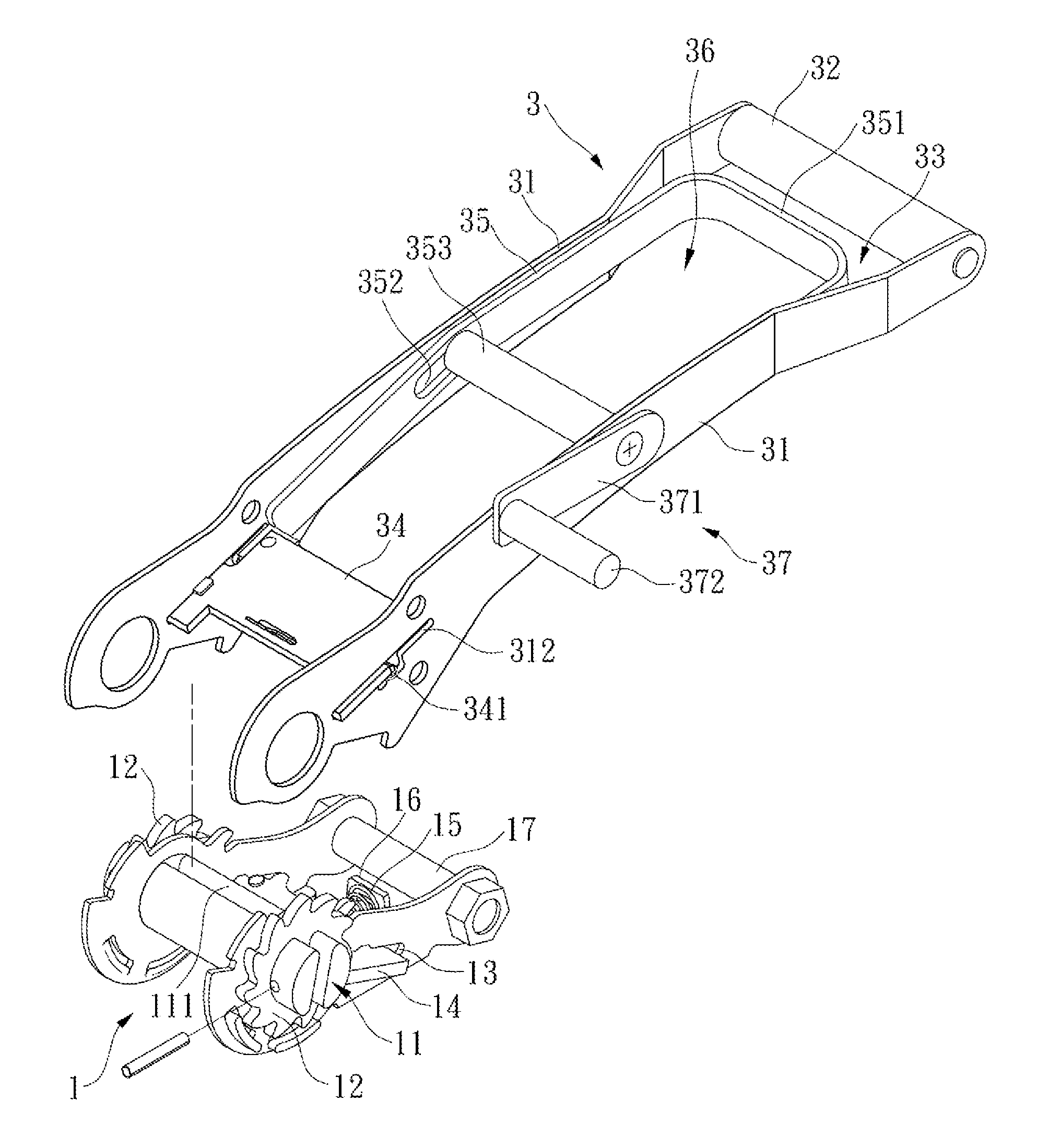
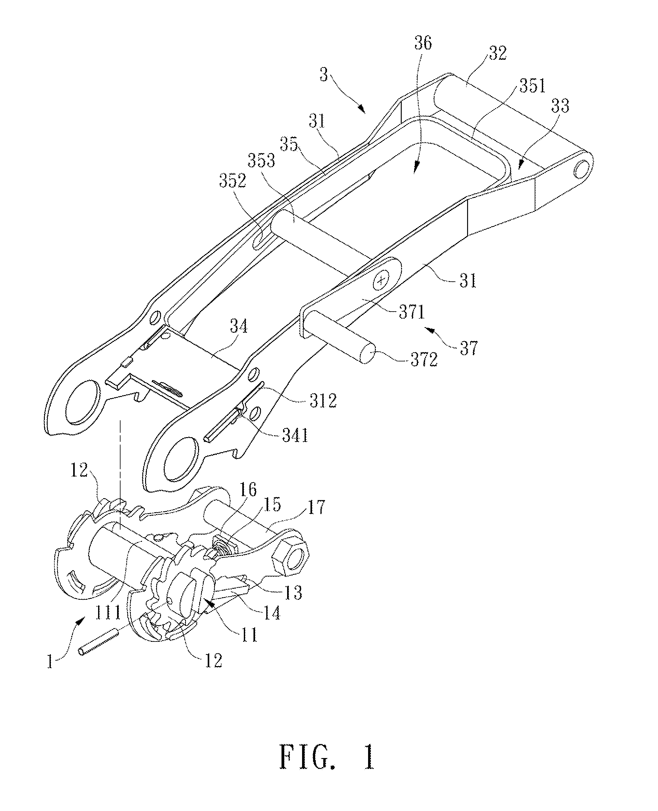
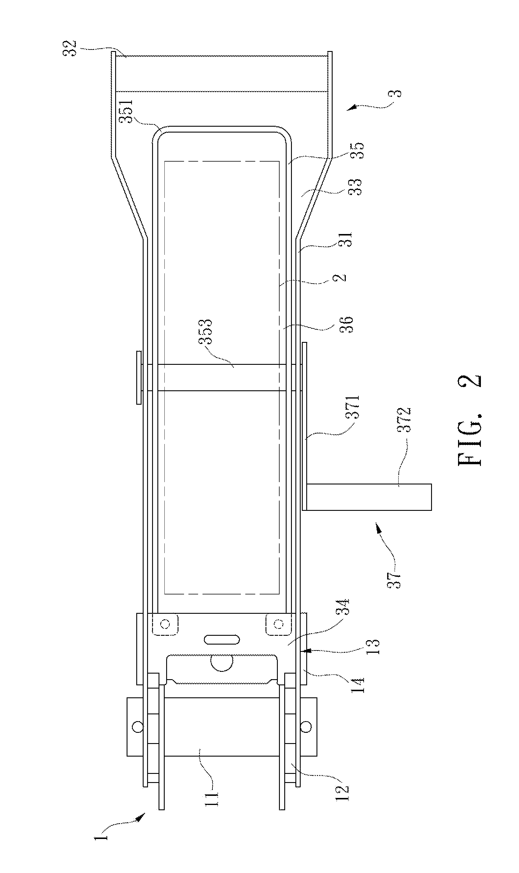
[0029]Please refer to FIGS. 1 to 4. The following paragraphs describe the invention. The embodiment includes a base 1 and a movable arm 3.

[0030]One end of the base 1 is pivotally connected with a pivotal element 11. The center of the pivotal element has a through hole 111 for a strap 2 to go through. The end parts of the pivotal element 11 going out of both sides of the base have respectively a ratchet wheel 12 rotating along with the rotating element 11. A first sliding groove 13 is formed on both sides of the base 1 near the two ratchet wheels 12. The two first siding grooves 13 is disposed with a first stopping plate 14 that can slide and urge against the two ratchet wheels 12. The side of the first stopping plate 14 far from the two ratchet wheels 12 is provided with a spring 15 for pushing the first stopping plate 14, so that the first stopping plate 14 urges against the two ratchet wheels 12. An extension board 16 is disposed between both sides of the bottom of the base 1. The...

second embodiment

[0037]Of course, the invention has many other embodiments that only differ in details. Please refer to FIG. 5 for the invention. The hand puller in this embodiment includes a base 4 and a movable arm 5.

[0038]One end of the base 4 is pivotally connected with a pivotal element 41. The center of the pivotal element has a through hole 411 for a strap 2 to go through. The end parts of the pivotal element 41 going out of both sides of the base have respectively a ratchet wheel 42 rotating along with the rotating element 41. A first sliding groove 43 is formed on both sides of the base 4 near the two ratchet wheels 42. The two first siding grooves 43 is disposed with a first stopping plate 44 that can slide and urge against the two ratchet wheels 42. The side of the first stopping plate 44 far from the two ratchet wheels 42 is provided with a spring 45 for pushing the first stopping plate 44, so that the first stopping plate 44 urges against the two ratchet wheels 42. An extension board 16...


PUM


Abstract

A hand puller whose handle can roll in a strap includes a base and a movable arm. The base has a pivotal element. The movable arm is disposed on the outer end of the pivotal element. A ratchet wheel is disposed between the movable arm and both ends of the base, respectively. The movable arm has a second stopping plate and extends with a pulling element. The pulling element has a third sliding groove with a rotating axis. Both ends of the rotating axis are disposed on the two arm boards of the movable arm. A rotating element is provided for the user to rotate, so that the strap is winded on the rotating axis.

Description

BACKGROUND OF THE INVENTION[0001]1. Field of Invention[0002]The invention relates to a hand puller that can roll in its strap and, in particular, to the structure of a hand puller that can conveniently roll in its strap.[0003]2. Related Art[0004]Generally speaking, one often uses a strap hand puller to fix or help fix a machine or cargo during the transportation. When the strap is not in use or too long, one has to wind it up or somehow collect it in a smaller space in order to avoid tying up. This is very inconvenient.[0005]As shown in FIGS. 6 and 7, a conventional hand puller includes a base 61. One end of the base 61 connects to a tightening mechanism 62 that has a movable arm 621 and a rotating axis 622 connected with the movable arm 621. The other end of the base 61 is installed with a strap roller 63. The strap 64 goes through the rotating axis 622 of the tightening mechanism 62 and connects onto the axis inside the strap roller 63 (not shown). Therefore, one can operate the m...

Claims


Application Information

Patent Timeline
Patent Type & Authority Applications(United States)
IPC IPC(8): A44B11/16A44B11/02
CPCY10T24/2175A44B11/125
Inventor LU, JUNG-WEN
Owner LU JUNG WEN
Learn More