
FPC fixing structure for two-axis hinge mechanism

Inactive Publication Date: 2011-06-23
MITSUBISHI ELECTRIC CORP
View PDF16 Cites 5 Cited by
  • Summary
  • Abstract
  • Description
  • Claims
  • Application Information

AI Technical Summary

Benefits of technology

[0007]The present invention has been made to solve the above-mentioned problems, and an object of the present invention is to provide an FPC fixing structure for a two-axis hinge mechanism capable of preventing an FPC from being damaged by the turning operation and the folding and unfolding operation of a monitor and also reducing stresses induced in flexing.
[0009]According to the present invention, the FPC is held linearly on the monitor turning axis and also the deflection allowance is provided outside the monitor turning axis. This can prevent the FPC from being damaged by the turning operation, and the folding and unfolding operation of the monitor, and can reduce the amount of flexure of the FPC. Further, providing the deflection allowance outside the monitor turning axis can ensure a large circular arc of the FPC to enable the reduction of stresses caused by the flexure of the FPC.

Problems solved by technology

For this reason, there are the following problems: the workability is deteriorated during the assembly of the FPC, and further the FPC is also increased in length.
Furthermore, the FPC is provided with a bend section for connecting a rotation section wound around the covering tube with a straight line section to be led out to the side of the main body; however, there is the problem such that when the FPC is twisted by the rotation of the rotation shaft, stresses are concentrated on the bend section of the FPC to be easily cut.
Further, since the straight line section is also affected by the twist, the FPC is easily displaced from a connector when an FPC connecting member such as a connector is used.
This occasionally causes difficulties in the electrical connection.
Because of this, there is the problem such that the FPC has the flexure life unbalanced in the turning section and the folding and unfolding section.

Method used


Image

  • FPC fixing structure for two-axis hinge mechanism
  • FPC fixing structure for two-axis hinge mechanism
  • FPC fixing structure for two-axis hinge mechanism

Examples


first embodiment

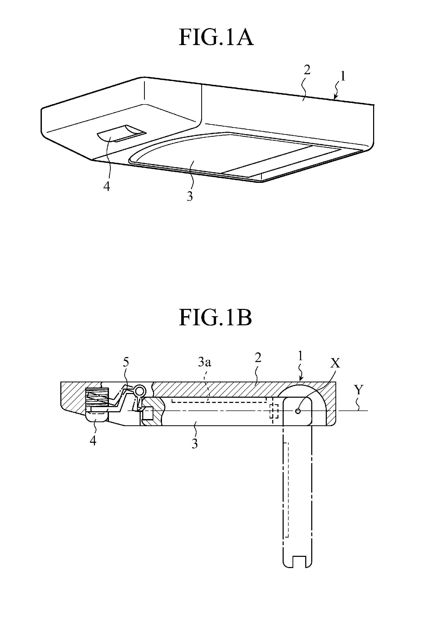
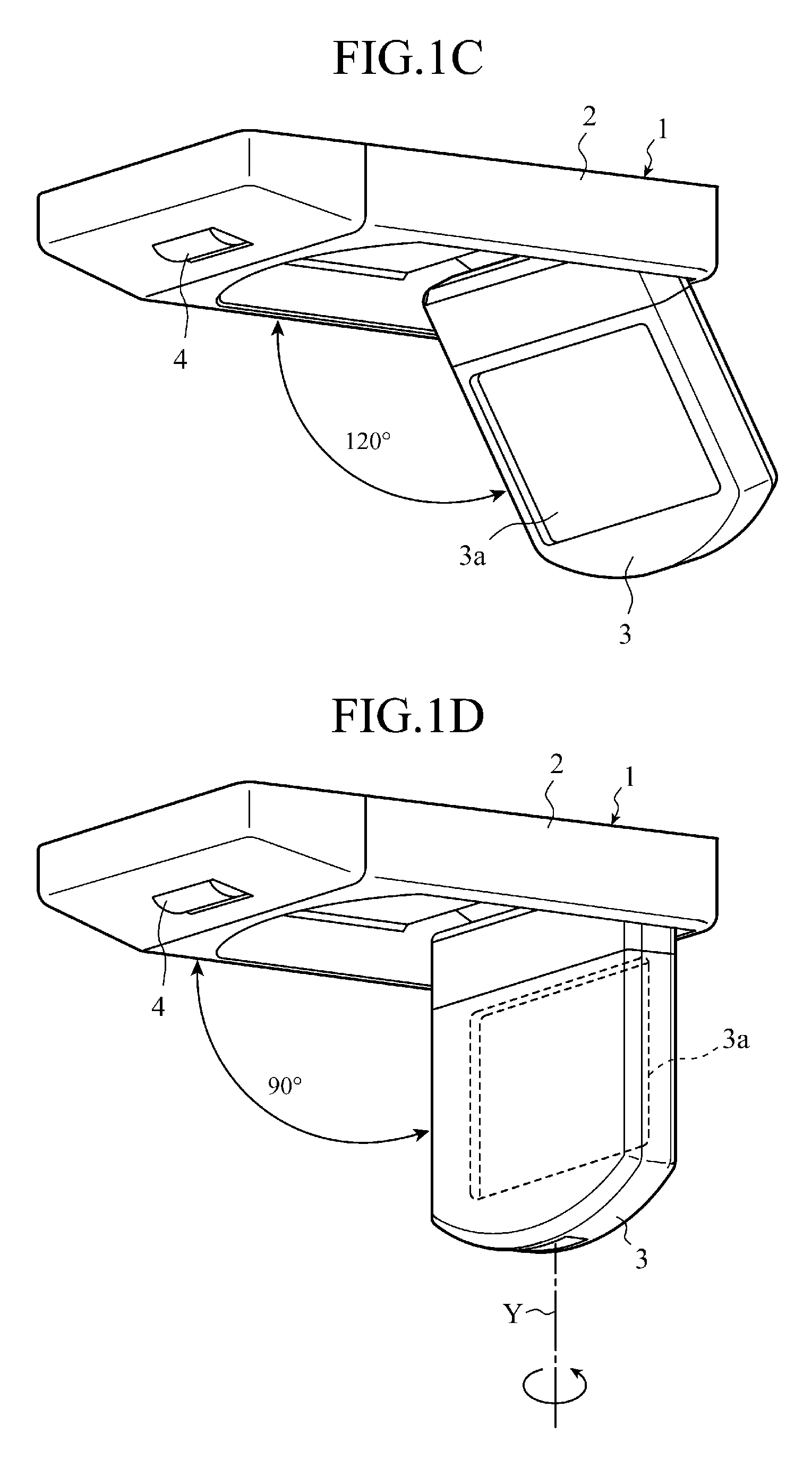
[0027]In a first embodiment, a two-axis hinge mechanism according to the present invention is applied to a monitor apparatus mounted on the ceiling of the interior of a vehicle. FIG. 1A to FIG. 1D are views showing a series of turning, and folding and unfolding operations of a monitoring apparatus 1 including a two-axis hinge mechanism 10 in accordance with the first embodiment. FIG. 1A is a perspective view showing a state where a monitor 3 is housed in a monitor housing case 2, and FIG. 1B is a sectional view thereof. FIG. 1C is a perspective view of a state where the monitor 3 is unfolded 120°, and FIG. 1D is a perspective view of a state where the monitor 3 is unfolded 90°.

[0028]As shown in FIG. 1A, the monitor apparatus 1 is composed of: the monitor housing case 2 on the side of a main boy apparatus mounted on the ceiling of a vehicle; and the monitor 3 that can be unfolded and folded when turned (opened and closed) with respect to the monitor housing case 2. The monitor 3 has ...


PUM


Abstract

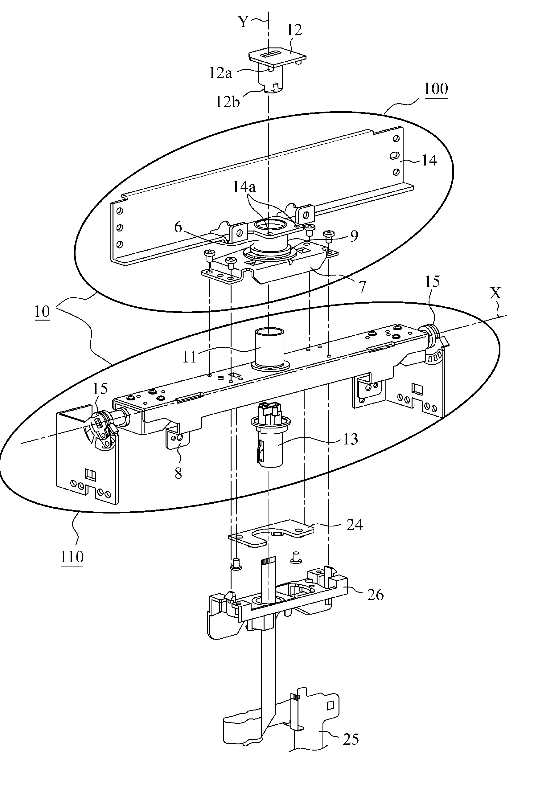
First and second FPC fixing members 12, 13 are fixed within a boss 6 on a second axis Y, and one end of the second member 13 projects to the back of a hinge base 8. An FPC wiring fixing section 26 is fixed on the back of the base 8 on a first axis X. The fixing members pass an FPC 25 from the base 8 side to the side of a monitor 3 to hold the FPC linearly on the axis Y, and are turned integrally with a monitor mounting base 14. The fixing members curve outside the axis Y the FPC 25 that is led out in the direction orthogonal to the axis Y from the one end on the base 8 side of the second member 13 to have a deflection allowance, and fix the FPC to the base 8.

Description

TECHNICAL FIELD[0001]The present invention is related to a fixing structure for wiring a flexible printed circuit board (hereinafter, referred to as an “FPC”) in a two-axis hinge mechanism for turning, and folding and unfolding a monitor.BACKGROUND ART[0002]A conventional FPC wired in a two-axis hinge mechanism has a structure where the FPC is wound about a rotation shaft of a hinge circumferentially to be fixed. As disclosed in Patent Document 1, for example, in a two-axis hinge mechanism for turnably, and foldably and unfoldably connecting a display to a main body, a rotation shaft of the hinge is covered with a covering tube, and an FPC is wound around the covering tube. The FPC is constructed in a fixing structure which does not interfere with the turning operation of the hinge mechanism, when the rotation shaft is forwardly or backwardly rotated within the covering tube as the display is turned by virtue of the FPC wound around the covering tube being wound up or being loosened...

Claims


Application Information

Patent Timeline
IPC IPC(8): E05D3/06
CPCB60R11/0235Y10T16/5472B60R2011/0082B60R2011/0087E05D3/10E05D11/0081E05Y2900/606G06F1/1681G06F1/1683H04M1/0212H05K1/028H05K2201/055H05K2201/10598E05Y2400/654E05Y2400/656Y10T16/557Y10T16/547B60R2011/0028E05Y2999/00
Inventor NAGAMI, TETSUROHAMADA, MANAMIKAMIMURA, TADASHI
Owner MITSUBISHI ELECTRIC CORP
Learn More