
Lens module

a technology of lens module and lens assembly, which is applied in the field of lens module, can solve the problems of high manufacturing cost, time-consuming assembly process, and inability to easily control the accuracy between the lens units b>1/b> of the two image capture devices b>1/b>, so as to shorten the time required for assembly and reduce the manufacturing cost. , the effect of reducing the steps of assembly

Inactive Publication Date: 2011-06-16
LUXVISIONS INNOVATION LTD
View PDF5 Cites 20 Cited by
  • Summary
  • Abstract
  • Description
  • Claims
  • Application Information

AI Technical Summary

Benefits of technology

[0008]Therefore, the main object of the present invention is to provide a lens module having two lens units respectively defining light communicating paths, so that efficiency and accuracy of assembly thereof may be enhanced, and the manufacturing cost thereof can be reduced to a minimum.
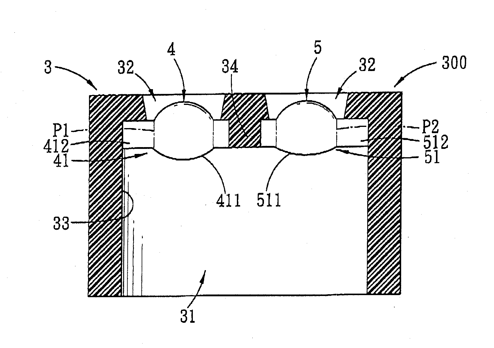
[0011]Through the aforesaid technical means, the advantages and efficacy of the lens module of the present invention reside in a left-to-right arrangement of the first and second lenses of the first and second lens units, and in the first and second light communicating paths defined respectively by the first and second lenses. Through such a configuration, steps of assembly can be reduced so as to shorten the time required for assembly, thereby reducing the manufacturing costs to a large extent. Further, assembly and positioning precision of the first and second lenses of the first and second lens units can be effectively enhanced, so that accuracy of the lens module after assembly on the electronic device may also be enhanced.

Problems solved by technology

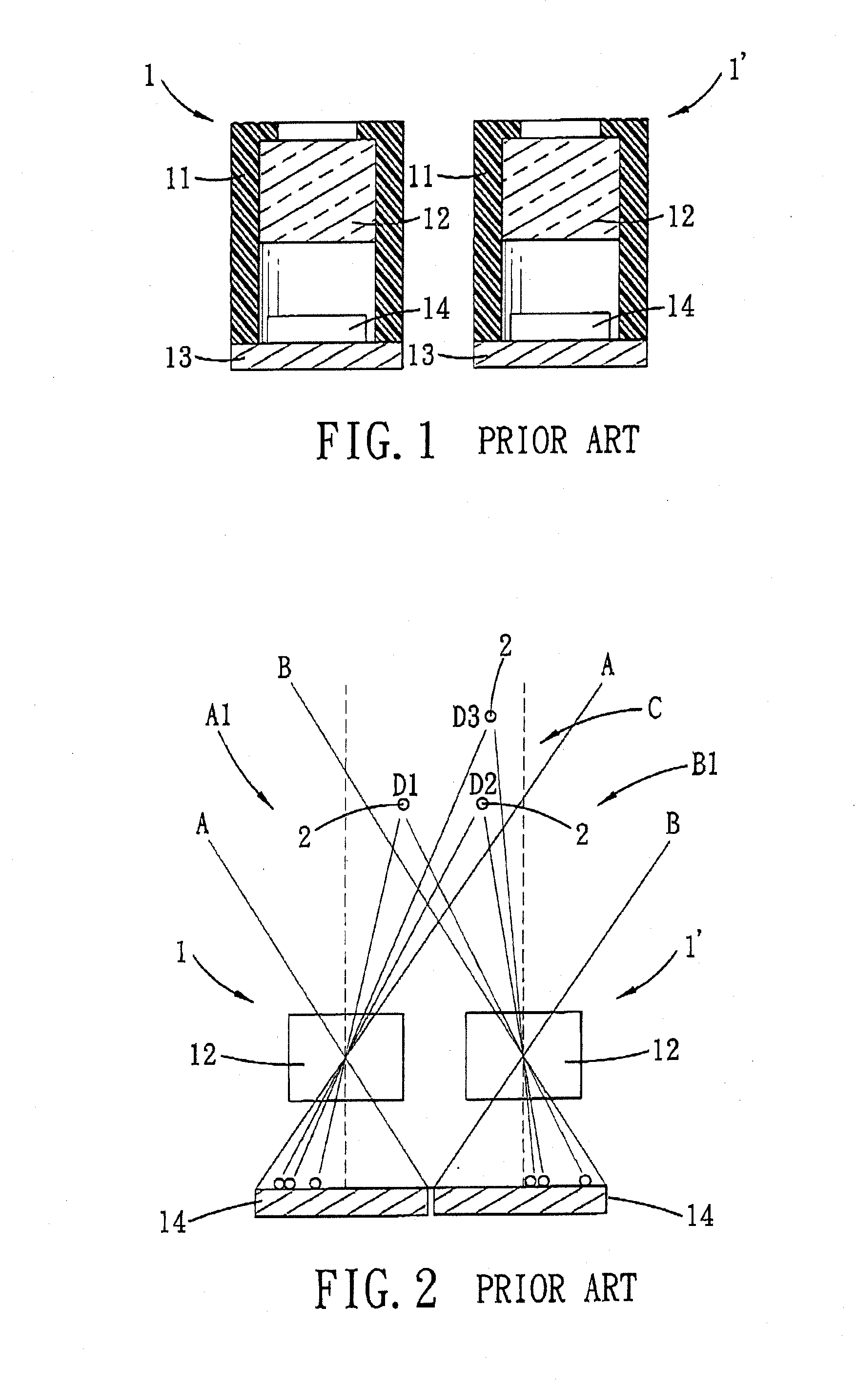
Since the image capturing devices 1, 1′ have to be separately manufactured, after which they are assembled on the electronic device, the assembly process thereof is time-consuming, and the manufacturing cost thereof is high.
Moreover, the components of each image capturing device 1, 1′ have specific assembly tolerances during assembly, so that accuracy between the lens units 12 of the two image capturing devices 1, 1′ after their assembly on the electronic device cannot be easily controlled.

Method used


Image

  • Lens module
  • Lens module
  • Lens module

Examples


Embodiment Construction

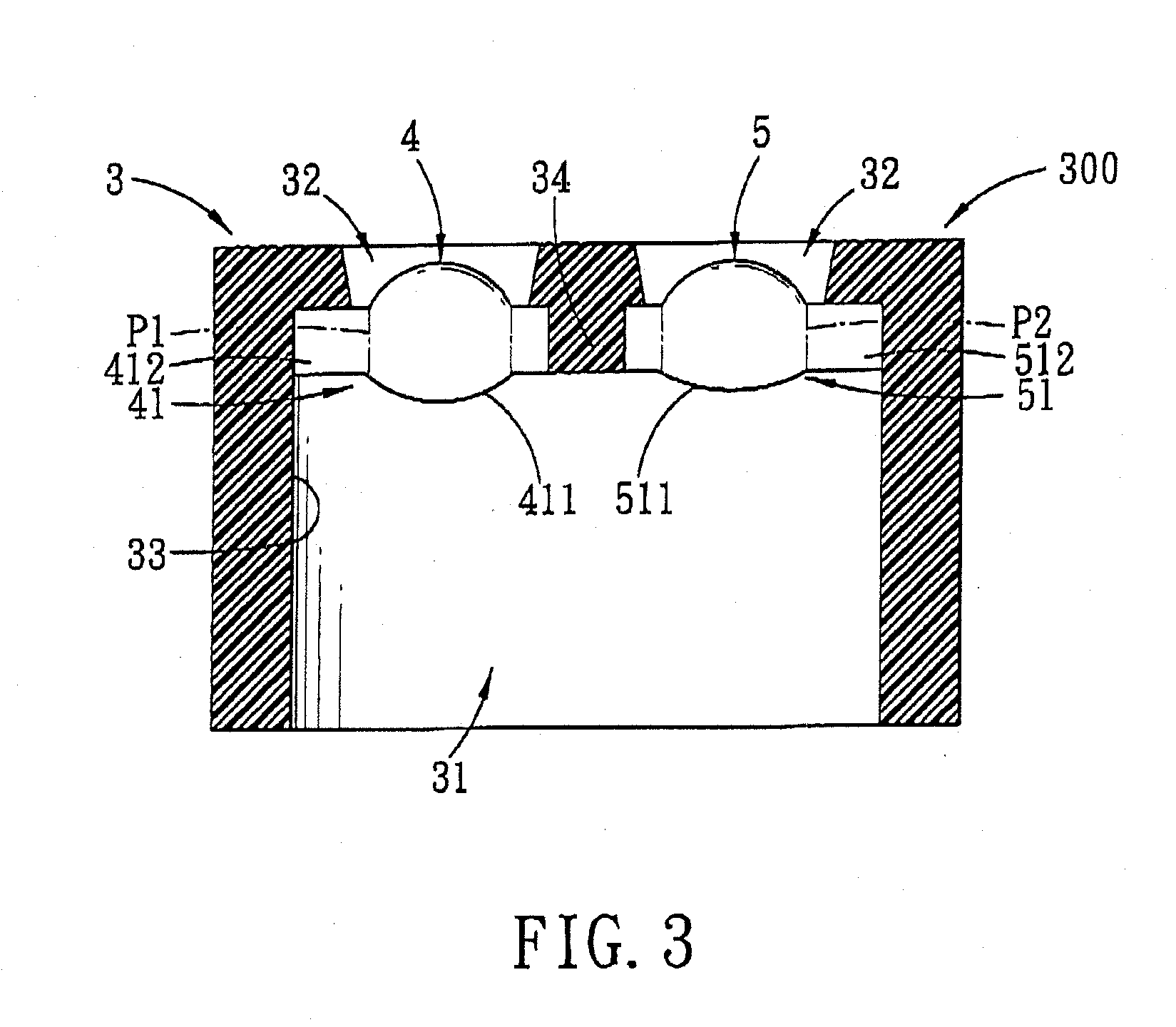
[0024]The above-mentioned and other technical contents, features, and effects of this invention will be clearly presented from the following detailed description of three preferred embodiments in coordination with the reference drawings. Through description of the concrete implementation method, the technical means employed and the efficacy to achieve the predetermined purpose of the present invention will be thoroughly and concretely understood. However, the enclosed drawings are used for reference and description only, and are not used for limiting the present invention.

[0025]Before this invention is described in detail, it should be noted that, in the following description, similar elements are designated by the same reference numerals.

[0026]Referring to FIG. 3, a lens module 300 according to the first preferred embodiment of the present invention comprises a base 3, a first lens unit 4, and a second lens unit 5.

[0027]The base 3 may be cylindrical or square shaped, is made of pla...


PUM


Abstract

A lens module includes a base, and first and second lens units. The base defines a receiving space, and has two spaced-apart through holes for fluid communication of the receiving space with an area external to the base. The first lens unit is disposed within the receiving space, and defines a first light communicating path that corresponds in position to one of the through holes. The second lens unit is disposed within the receiving space in a side-by-side manner with the first lens unit, and defines a second light communicating path that corresponds in position to the other one of the through holes.

Description

CROSS-REFERENCE TO RELATED APPLICATION[0001]This application claims priority of Taiwanese Application No. 098142867, filed on Dec. 15, 2009.BACKGROUND OF THE INVENTION[0002]1. Field of the Invention[0003]This invention relates to a lens module, more particularly to a lens module having two lens units respectively defining light communicating paths.[0004]2. Description of the Related Art[0005]Referring to FIGS. 1 and 2, currently, to determine the coordinate position of an object in a three dimensional space, at least two spaced-apart image capturing devices 1, 1′ are required to perform an image capturing operation. Both of the two image capturing devices 1, 1′ are simultaneously assembled on an electronic device (not shown). Each image capturing device 1, 1′ includes a base 11, a lens unit 12 fixed within the base 11, a circuit board 13 welded to a bottom end of the base 11, and a sensor element 14 provided on a top face of the circuit board 13 and spaced apart from and disposed be...

Claims


Application Information

Patent Timeline
Patent Type & Authority Applications(United States)
IPC IPC(8): G02B7/02
CPCG02B7/021G01S5/163
Inventor KUO, MENG-HSIN
Owner LUXVISIONS INNOVATION LTD
Learn More