
Three Stage, Multiple Phase Anaerobic Digestion System and Method

an anaerobic digestion and multiple phase technology, applied in the field of three stage, multiple phase anaerobic digestion system and method, can solve the problems of slow reproducibility of methanogens, rate-limiting steps, anaerobic process, etc., to increase the organic degradation and methane gas production rate, improve the reliability, and simplify the operation requirements

Inactive Publication Date: 2011-06-09
ADVANCED BIO ENERGY DEV
View PDF24 Cites 16 Cited by
  • Summary
  • Abstract
  • Description
  • Claims
  • Application Information

AI Technical Summary

Benefits of technology

[0030]This disclosure describes a three stage, multiple phase anaerobic biotechnology process designed to (1) significantly simplify the operational requirements, (2) significantly increase the reliability, and (3) significantly increase the organic degradation and methane gas production rates. The ultimate design goal of this invention is to make anaerobic digestion a reliable and profitable source of methane gas as a renewable energy source.

Problems solved by technology

Since the hydrolysis step is required to treat raw particulate matter, it often is a rate-limiting step in the anaerobic process due to the difficulty of digesting these often complex substrates (Sanders, et al.
Methanogens also are slow in reproducing, prefer a basic pH, and tend to be negatively affected by potential toxins such as heavy metals, solvents, pesticides and herbicides.
Methanogens are also adversely affected by relatively small changes in environmental factors, such as pH and temperature.
The production of energy has not been the primary goal of these systems.
First, the hydrolysis bacteria and acidogenic bacteria (acidogens) have pH optimums of 5.5 to 6.5; whereas the methanogenic bacteria (methanogens) have pH optimums of 7.8 to 8.2 (Khanal, 2008). This presents challenges with using a single stage reactor (digestion tank) because hydrolysis begins immediately when the raw organic feedstock enters the digestion tank. Hydrolysis causes a rapid drop in pH as acidic products such as organic acids are rapidly produced. This acidic pH in turn inhibits the growth and metabolic activity of the methanogens.
Since the hydrolysis phase is facilitated by acid conditions, raising the pH to satisfy the requirement of the methanogens can inhibit the rate of hydrolysis, making operation of the digester a precarious balancing act requiring trained and alert operators.
No matter how skilled the operator is, effectively combining efficient digestion and energy production has been virtually impossible in such a conventional digester.
Second, methanogenic organisms are slow reproducers and do not compete well for attachment space with the more robust and aggressive hydrolysis and acidogenic populations.
Due to the large tank sizes typically used, these elevated temperatures require the utilization of significant amounts of energy (to heat the digestion tank), often reducing the net energy output of the anaerobic digestion system by as much as fifty percent (50%) or more.
Fourth, heavy metals or other toxins introduced into the single reactor with the feedstock come into immediate and direct contact with the environmentally sensitive methanogens.
This is a frequent contributor to digester problems and reduction or cessation of methane (CH4) production.
Fifth, each time digested solids are discharged from the single digestion tank, a portion of the valuable, but slowly reproducing, methanogens, which are attached to the solid particles, are also lost.
Seventh, these operational challenges require a highly trained and attentive operational staff to properly operate conventional digesters.
Such staff is in short supply.
However, none of these have solved the operational sensitivity problems, nor have they significantly increased biogas yields or biogas purity as evidenced by the low numbers of full-scale multi-stage installations which have been constructed.
Fifth, there is a large, albeit inefficient, pre-existing installed base of single stage digesters, for instance it has been estimated that there are 12,000 to 16,000 individual digester tanks in the United States and over 20,000 in Europe.

Method used


Image

  • Three Stage, Multiple Phase Anaerobic Digestion System and Method
  • Three Stage, Multiple Phase Anaerobic Digestion System and Method
  • Three Stage, Multiple Phase Anaerobic Digestion System and Method

Examples


second embodiment

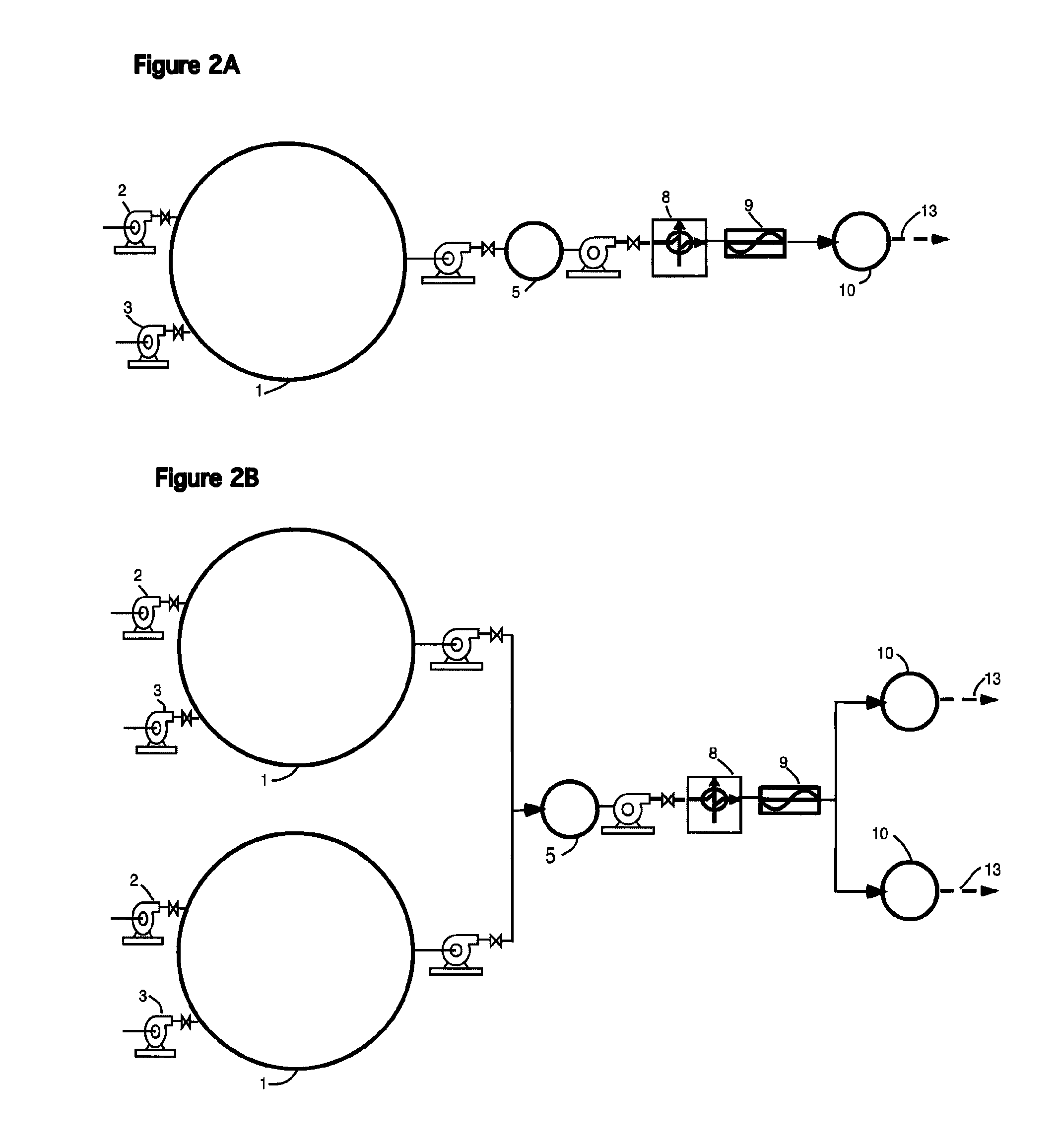
[0041]FIG. 2A shows a FIG. 2A showing a single Stage I, a single Stage II, and a single Stage III, all in a series configuration. This type of implementation may be best for smaller systems.

third embodiment

[0042]FIG. 2B shows a FIG. 2B showing dual Stage I and Stage III, with a single Stage II. This embodiment is used with alternating mixing and feed from dual Stages I to single Stage II, and alternating feed from single Stage II to the dual Stage III's for larger systems.

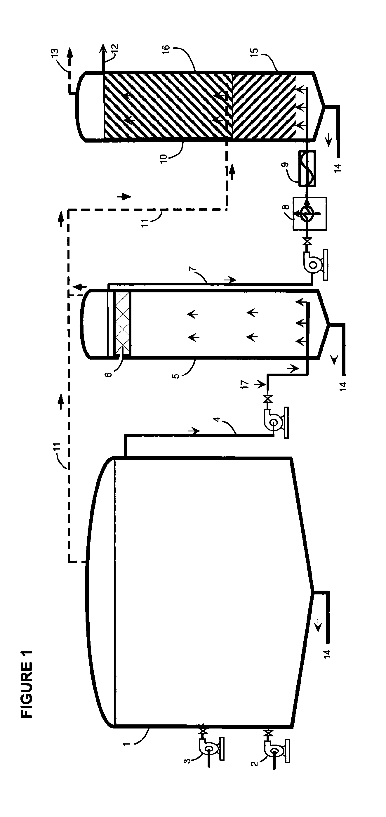
[0043]Stage I takes place in the primary (first) digestion tank 1. It is preferably similar in size and configuration to that used in conventional single stage anaerobic digestion systems. Stage I is operated as a complete mix reactor wherein a feed pump 2 injects raw feedstock into the Stage I digestion tank 1. The primary digestion tank 1 is provided with at least one mixing means 3 (e.g., mechanical mixer, internal hydraulic jet nozzles, external chopper pumps) for mixing the contents of the primary digestion tank 1 and for causing rapid size reduction of the raw organic solids contained in the feedstock. This mixing and size reduction preferably uses the Liquid Dynamics Jetmix® systems.

[0044]Stage I is optimized...

example implementation

[0073] Injecting raw feedstock into a primary digestion tank; mixing the contents of the primary digestion tank mechanically, thereby reducing the size of the raw organic solids contained in the feedstock; holding feedstock in the digestion tank for a predetermined period of time to provide for extensive but incomplete microbial hydrolysis; ceasing mixing to allow for settling of denser solids; drawing off a supernatant from the upper portion of the contents of the primary digestion tank; pumping said supernatant to a second digestion tank; collecting gases from the first digestion tank and transmitting said gasses to the base of a third digestion tank; draining undigested material from the bottom of the first digestion tank; maintaining the first digestion tank and second digestion tank at a temperature of 24° C. to 35° C.; operating the second digestion tank as an upflow fluidized bed reactor; adjusting upflow velocity to that which will minimize overflow of the suspended solids t...


PUM

PropertyMeasurementUnit
pHaaaaaaaaaa
temperatureaaaaaaaaaa
pHaaaaaaaaaa

Abstract

A three stage, multiple phase anaerobic digestion system and method designed to separate the biological phases, optimize microbial activity in each phase, and significantly increase system reliability and energy production. The system physically separates the biological phases of anaerobic digestion based on particle size, particle density, and solubility of metabolic products. The system allows a complex multi-phased biological system to develop without the need for excessive control or operator intervention.

Description

BACKGROUND OF THE INVENTION[0001]Anaerobic digestion refers to both a natural microbial process, which takes place in the absence of oxygen, and, an engineered process, which utilizes the microbial process. Both produce methane gas (CH4) as an end product. Anaerobic digestion is of great interest today due to its potential as a renewable energy source.[0002]There is much confusion regarding the use of the terms “stage” and “phase” in the anaerobic digestion literature. Numerous authors have used the terms interchangeably. However, as used herein, the term “phase” is used to refer to biological steps in the anaerobic digestion process, whereas the term “stage” refers to an engineered physical entity (e.g., tank, container) used to contain the microbial phases.[0003]The term “feedstock,” also referred to as influent, refers to liquid and solid material fed into a an anaerobic digester, including but not limited to dairy manure / waste, municipal and industrial waste water sludge, organi...

Claims


Application Information

Patent Timeline
Patent Type & Authority Applications(United States)
IPC IPC(8): C02F3/34C12M1/00
CPCC02F3/286C12M21/04C12M23/58C12M45/06C12P5/023C12M21/12B09C1/10C02F3/34C12M25/18C12P1/00Y02E50/343Y02E50/30
Inventor STEWART, WILLIAM C
Owner ADVANCED BIO ENERGY DEV
Learn More