
System and process for client driven automated circuiting and branch circuit wiring

a technology of automated circuits and circuit wiring, applied in the field of system and process for client-driven automated circuits and branch circuit wiring, can solve the problems of insufficient detail of architectural drawings to develop cost estimates, and none at all

Inactive Publication Date: 2011-05-26
STEBNICKI GERRY +3
View PDF2 Cites 7 Cited by
  • Summary
  • Abstract
  • Description
  • Claims
  • Application Information

AI Technical Summary

Benefits of technology

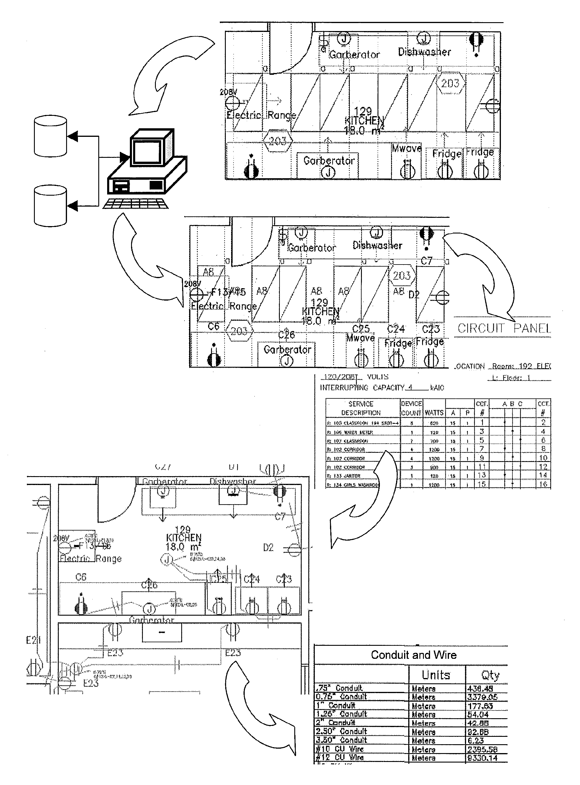
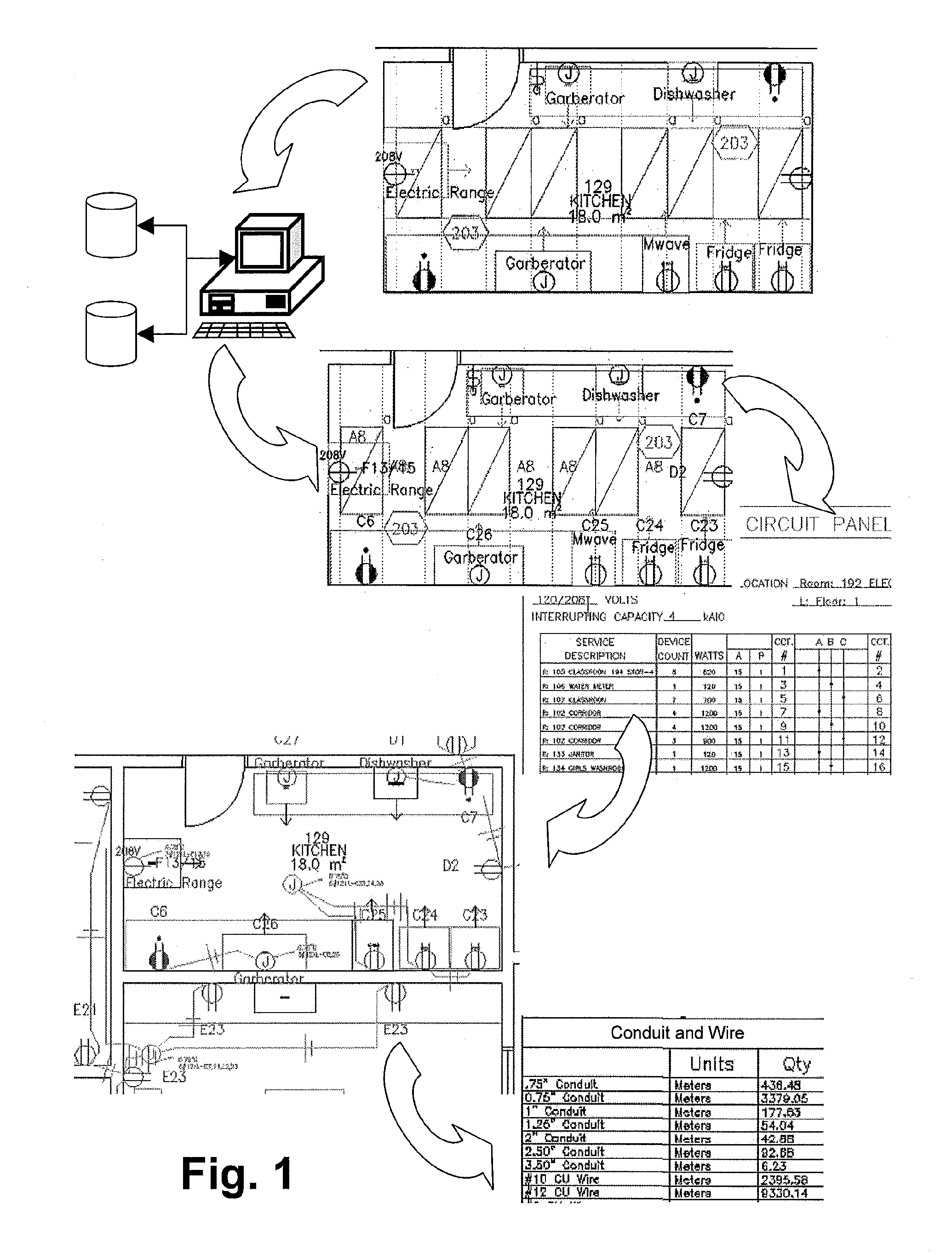
[0013]The present invention is a process for automated electrical circuiting, branch circuit wiring and production of detailed engineering CAD drawings from a client's architectural drawings. Architectural drawings are not generally sufficiently detailed for one to develop a cost estimate, to direct the actions of a construction contractor, nor to establish compliance with electrical standards, to name a few. Not only does an architectural drawing comprises a multitude of drawings elements but it also comprises assets formed of such drawings elements including corridors, rooms and utility rooms, all of which have different requirements for electrical and mechanical services, standards and compliance. Herein, application of the automated electrical circuiting or branch circuit wiring, or both can result in reductions in significant reductions in design time, design cost, optimization of electrical circuit grouping and routing and minimization of material use with the resulting savings associated therewith. Further, the system and process can prepare electrical engineering drawings and schedules where, in many instances, none would be prepared at all due the overwhelming options and cost for completing a comprehensive branch circuit wiring.

Problems solved by technology

Architectural drawings are not generally sufficiently detailed for one to develop a cost estimate, to direct the actions of a construction contractor, nor to establish compliance with electrical standards, to name a few.
Further, the system and process can prepare electrical engineering drawings and schedules where, in many instances, none would be prepared at all due the overwhelming options and cost for completing a comprehensive branch circuit wiring.

Method used


Image

  • System and process for client driven automated circuiting and branch circuit wiring
  • System and process for client driven automated circuiting and branch circuit wiring
  • System and process for client driven automated circuiting and branch circuit wiring

Examples


example

[0114]The process of the present invention was applied during the design and construction of a one level school in Canada. With reference FIGS. 5, and 6, the end user loaded an engineering drawing 500 drawing having at least one electrical building system device and the appropriate module for a school in Canada was selected to be applied to the project.

[0115]In preparation for automated circuiting, lighting and receptacles were selected for automated circuiting. The west side of the school was then selected to be circuited and panel room 503 was determined to be the location for all the panels for the services on the west side of the school.

[0116]With references to FIGS. 7 and 8, with automated circuiting now completed, the receptacles 501 and the lighting components 502 in each room was circuited and assigned to a specific circuit. As shown in FIG. 7, receptacles 501 in classroom 111 were assigned to circuit C10 while the lighting components in classroom 111 were assigned to circui...


PUM


Abstract

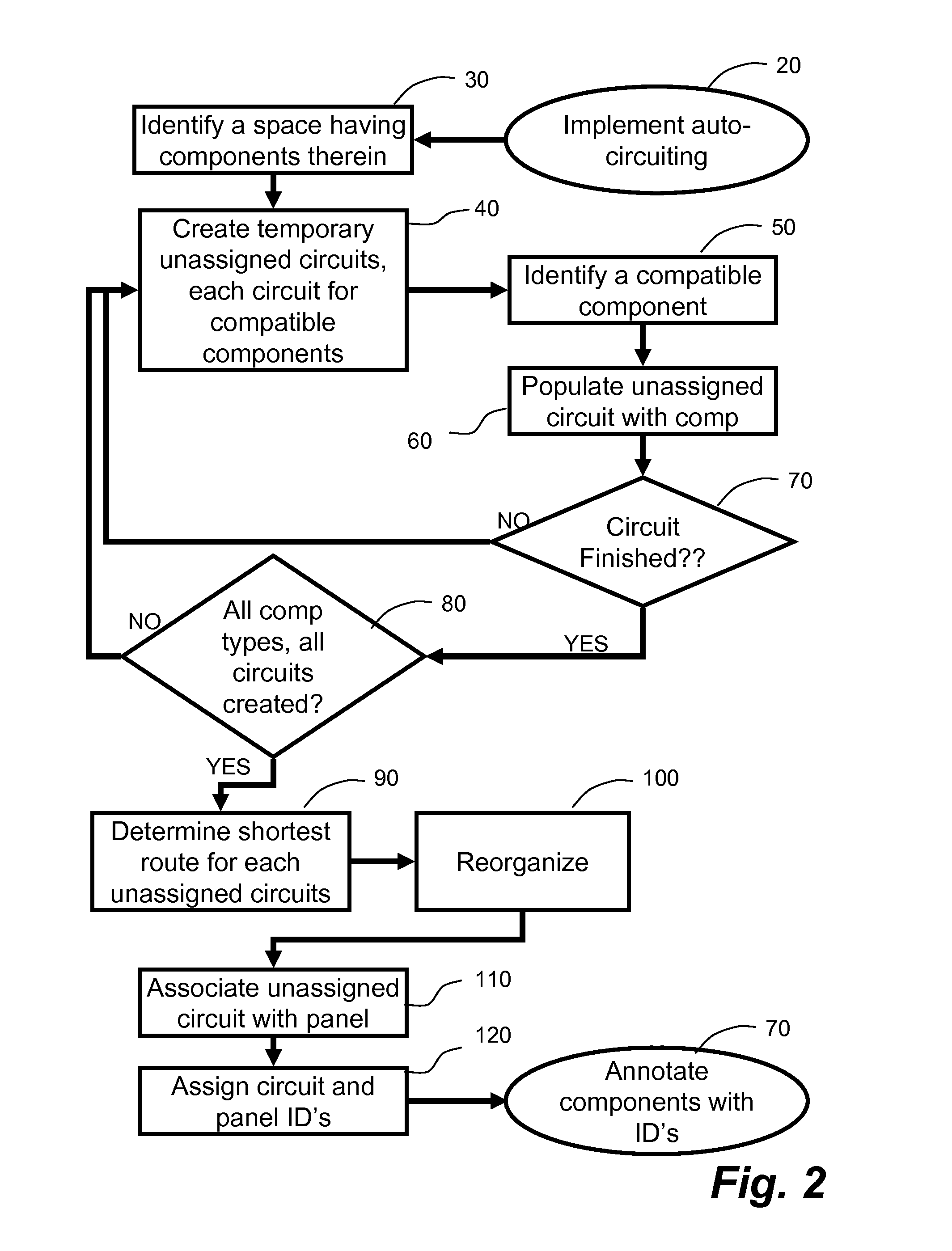
A computer aided design application modifies a CAD drawing having one or more electrical components by optimizing a plurality of circuits and associated panels, and assigning circuit and panel identifiers to each component for producing an engineering drawing. Further such identified components can be placed in home run groups, implementing shortest path calculations for various wire types and using neutral wires sharing options for producing an engineering drawing illustrating the home run grouping and identifiers, panel schedules and complete bills of materials.

Description

FIELD OF THE INVENTION[0001]The invention relates to a system for receiving a raw computer assisted drawing (CAD), and forming a detailed computer-automated circuiting and branch circuit wiring drawing, the content of which complies with regulatory and client criteria. More particularly, a client supplies a CAD drawing including building electrical systems components and the system adds the necessary panels, assigns circuits for updating the CAD drawing including panel schedules and further can draw branch circuit wiring interconnections between the components.BACKGROUND OF THE INVENTION[0002]In one context, a building design, in the form of architectural drawings (preliminary drawings), is provided to an engineer or design professional who applies codes, standards and rules to prepare and adjust the building design as necessary to ensure regulatory compliance and to meet the client's individual requirements. During this process, the design professional generates sufficient detail f...

Claims


Application Information

Patent Timeline
IPC IPC(8): G06F17/50
CPCG06F17/509G06F30/18
Inventor STEBNICKI, GERRYSMITH, TERRYWHITFORD, DEANHATFIELD, RICHARD
Owner STEBNICKI GERRY
Learn More