Multistage electric power generating and ventilating device
- Summary
- Abstract
- Description
- Claims
- Application Information
AI Technical Summary
Benefits of technology
Problems solved by technology
Method used
Image

Examples
Embodiment Construction
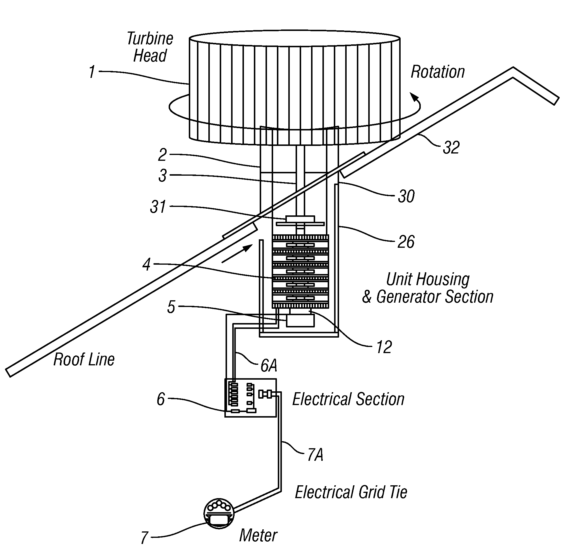
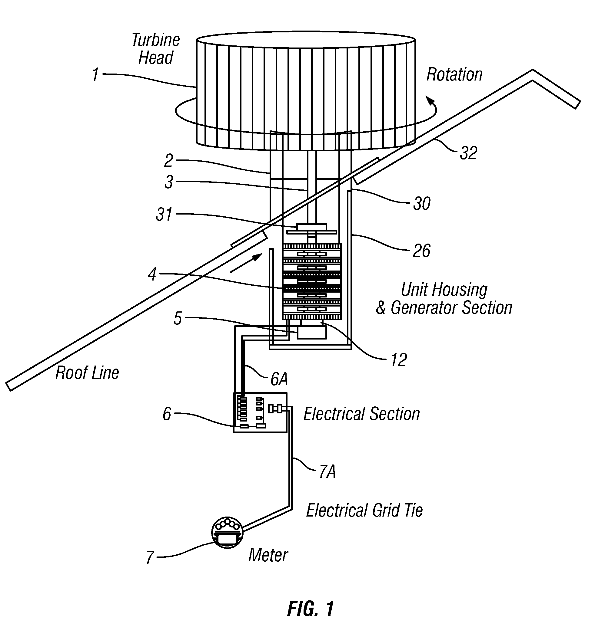
[0017]FIG. 1 shows an example turbine generator and ventilation system according to the invention. The example system includes a turbine head 1 rotatably connected to a through duct or conduit 2 and a connecting drive shaft 3. The conduit 2 may be configured to pass through a suitable opening 30 in a roof 32 such as may be at the top of a residential structure. The turbine head 1 converts wind energy into rotational energy, and the connecting shaft 3 transfers the rotational energy to a generator 4. The generator 4 further connects to a shaft speed measuring device (i.e., a tachometer) 12 and an electric motor 5. The generator 4 is connected to circuit sub section 6 with electrical wiring 6A. The electrical sub section 6 is connected to a meter and electrical grid 7 with electrical circuit wiring 7A. The system of the present invention may provide continuous ventilation in all wind conditions, including in low or zero wind conditions by using an electric motor 5 coupled to the shaft...
PUM
 Abstract
Description
Claims
Application Information
 - R&D
- Intellectual Property
- Life Sciences
- Materials
- Tech Scout
- Unparalleled Data Quality
- Higher Quality Content
- 60% Fewer Hallucinations
Browse by: Latest US Patents, China's latest patents, Technical Efficacy Thesaurus, Application Domain, Technology Topic, Popular Technical Reports.
© 2025 PatSnap. All rights reserved.Legal|Privacy policy|Modern Slavery Act Transparency Statement|Sitemap|About US| Contact US: help@patsnap.com