
Graft pulley and methods of use

Inactive Publication Date: 2011-05-19
ARTHROCARE
View PDF162 Cites 39 Cited by
  • Summary
  • Abstract
  • Description
  • Claims
  • Application Information

AI Technical Summary

Benefits of technology

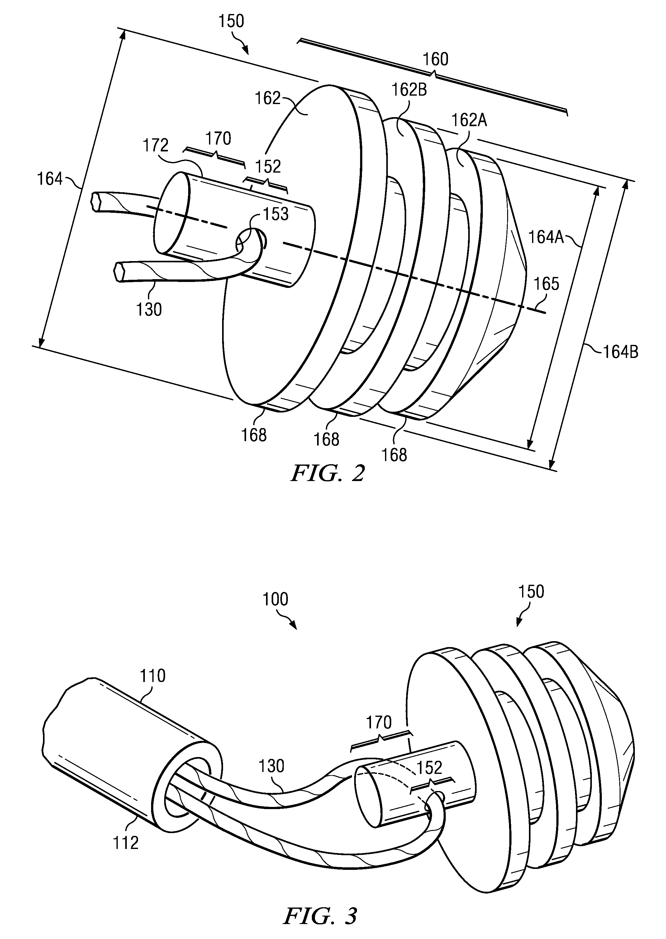
[0007]The present disclosure presents an improved placement assembly for positioning a ligament graft within a selected bone tunnel. The assembly includes a surgical suture which may be assembled with a graft pulley, and a graft pulley placement instrument removably connected with said graft pulley. The graft pulley has a pulley portion and a bone anchoring portion. The pulley portion includes an aperture or channel sized to receive the surgical suture, so that the surgical suture may be drawn through the aperture, to act as a pulley. The bone anchoring portion includes at least one flexible wing that is adapted to selectively fix the graft pulley within a bone tunnel. The placement instrument is adapted to place the graft pulley within the bone tunnel and also to assist in fixing it within the bone tunnel and the instrument includes a handle and elongate body. Once the graft pulley is in place, the instrument may then be detached from the graft pulley and withdrawn from the bone tunnel.
[0011]A further aspect of a graft pulley is disclosed for positioning a ligament graft within a selected bone tunnel. The bone tunnel has a blind end that is spaced substantially from the capsule of the bone that the tunnel is disposed. The graft pulley includes a pulley portion with an aperture that is sized to receive at least one surgical suture, as well as a bone anchoring portion, which may be selectively advanced into the blind end of the selected bone tunnel, so that a portion of the bone anchoring portion is disposed within the bone tunnel blind end to secure the graft pulley in position. The graft pulley is sized so as to not engage or violate the bone tunnel walls during insertion. The bone anchoring portion may include a self tapping tip that may be advanced or screwed beyond the bone tunnel blind end to fix the graft pulley within the bone tunnel blind end. A pilot hole may be present within the bone tunnel blind end to help guide the self tapping tip.
[0015]The present disclosure includes a number of important technical advantages. One technical advantage is that the pulley may be precisely, quickly and easily slid into place. Another advantage is that the pulley may not cause any significant trauma to the bone tunnel wall during insertion as well as during fixation. Another advantage is that this invention does not require an incision in the anterior femur, reducing the trauma to the femur and likelihood of an additional wound site infection, unsightly markings of the incision site and interference with tourniquets or equipment used during surgery. Another advantage is that the graft pulley may be placed closer to where the graft may be anchored, potentially reducing the length of sutures required for the procedure, and thereby reducing the complexity of the procedure. Another advantage is that the graft may be easily positioned within the bone tunnel without extra placement equipment. Additional advantages will be apparent to those of skill in the art and from the figures, description and claims provided herein.

Problems solved by technology

The button is typically located external to the knee, close to the bone tunnel exit on the femur and there are numerous disadvantages associated with to this button and the button's location.
Firstly, this external location is some distance from the site where the graft may be fixed within the bone tunnel, which makes positioning the graft more difficult and requires additional lengths of sutures to attach the graft to this button.
The button also necessitates the extension of the bone tunnel through the femur skin and quadriceps muscle, causing additional trauma to the leg and the increased potential for infections or nerve damage.
It is also considered less cosmetically desirable.
This external button may also cause interference with the tourniquet used during the surgical procedure.

Method used


Image

  • Graft pulley and methods of use
  • Graft pulley and methods of use
  • Graft pulley and methods of use

Examples


Embodiment Construction

[0029]Before the present invention is described in detail, it is to be understood that this invention is not limited to particular variations set forth herein as various changes or modifications may be made to the invention described and equivalents may be substituted without departing from the spirit and scope of the invention. As will be apparent to those of skill in the art upon reading this disclosure, each of the individual embodiments described and illustrated herein has discrete components and features which may be readily separated from or combined with the features of any of the other several embodiments without departing from the scope or spirit of the present invention. In addition, many modifications may be made to adapt a particular situation, material, composition of matter, process, process act(s) or step(s) to the objective(s), spirit or scope of the present invention. All such modifications are intended to be within the scope of the claims made herein.

[0030]Methods ...


PUM


Abstract

A placement assembly used for positioning and holding a ligament graft within a selected bone tunnel. The assembly includes a graft pulley, a surgical suture, and a graft pulley placement instrument. The graft pulley includes a pulley portion and a bone anchoring portion. The pulley portion is adapted to receive the surgical suture and for surgical suture to be drawn through it, to act as a pulley. The bone anchoring portion comprises a portion adapted to selectively fix the graft pulley within a bone tunnel. The graft instrument may be selectively attached to the graft pulley and includes a handle and elongate body, adapted to insert the graft pulley into the selected bone tunnel. Once the graft pulley is in place, the placement instrument may then be detached and withdrawn leaving the graft pulley firmly fixed within the bone tunnel and can then be used to position a ligament graft.

Description

CROSS-REFERENCE TO RELATED APPLICATIONS[0001]This application is a continuation-in-part of U.S. application Ser. No. 12 / 619,167, filed Nov. 16, 2009, and entitled “Graft Pulley and Methods of Use,” hereby incorporated herein by reference.FIELD OF THE INVENTION[0002]The present invention relates generally to an apparatus and method for positioning a ligament graft, and more particularly to an implantable graft pulley adapted to firmly fix within a selected bone tunnel and assist the positioning of a graft within said bone tunnel.BACKGROUND OF THE INVENTION[0003]One of the most common sports injuries to the knee involves a tearing or detachment of the anterior cruciate (ACL) ligament in the knee. Over the years, surgery to repair this injury has evolved from open reduction surgical procedures on the knee, to less invasive techniques. The goal of the surgery is to attach a graft ligament, between the femur and the tibia. Various grafts may be used, including bone-tendon-bone grafts, so...

Claims


Application Information

Patent Timeline
IPC IPC(8): A61F2/08
CPCA61F2002/087A61F2002/0882A61B17/0401A61B17/0483A61B2017/0409A61F2/0811A61B2017/0414A61B2017/0427A61B2017/044A61F2/08A61F2/0805A61B2017/0412
Inventor DELLI-SANTI, GEORGEWOLF, ALAN W.
Owner ARTHROCARE
Learn More