
Method and apparatus for gas flow control

a flow control and flow rate technology, applied in the direction of engine diaphragms, diaphragm valves, instruments, etc., can solve the problems of difficult change or control of the physical properties of the gas and the temperature of the system, unable to monitor or control the characteristics of critical orifice devices, and the actual flow rate through the mfc can drift to unacceptable values, etc., to achieve a high degree of precision

Inactive Publication Date: 2011-05-12
PIVOTAL SYST CORP
View PDF23 Cites 60 Cited by
  • Summary
  • Abstract
  • Description
  • Claims
  • Application Information

AI Technical Summary

Benefits of technology

[0024]Embodiments of the present invention provide for a controllable flow restriction in which the dimensions of the flow restriction are measurable and controllable to a very high degree of precision. The measur

Problems solved by technology

In the case of the semiconductor industry, metering must be especially accurate, because deviations in the flow rate of only several percent can lead to process failures.
In general, the physical properties of the gas and the temperature of the system are difficult to change or control, so flow is controlled by varying the pressures in the system, the dimensions of the flow restriction, or both.
Without regular calibration, the actual flow rate through the MFC can drift to unacceptable values due to errors in the flow measuring device.
The critical orifice device does not monitor or control the characteristics of the flow restriction beyond assuming they are constant.
In terms of process variables, pressure is both observable and controllable by the device, while flow restriction is not controllable or observable.
This type of perturbation cannot be measured by the system, and therefore, cannot be corrected without the aid of an external calibration.
For both types of flow control devices described above, which together comprise the vast majority of flow control devices used in the semiconductor industry, there are not sufficient process variables to accomplish these tasks.
Neither of these flow control device types, however, allows self-calibration during operation.
The technological challenges in making this type of control valve that is accurate enough for the semiconductor industry become apparent from an order-of-magnitude estimate of the precision required.
In fact, except for high precision metering valves, which are not well suited for the cost, space, cleanliness, and reliability requirements of semiconductor manufacturing, very little work has been done to implement control valves with measureable and controllable restrictions.

Method used


Image

  • Method and apparatus for gas flow control
  • Method and apparatus for gas flow control
  • Method and apparatus for gas flow control

Examples


Embodiment Construction

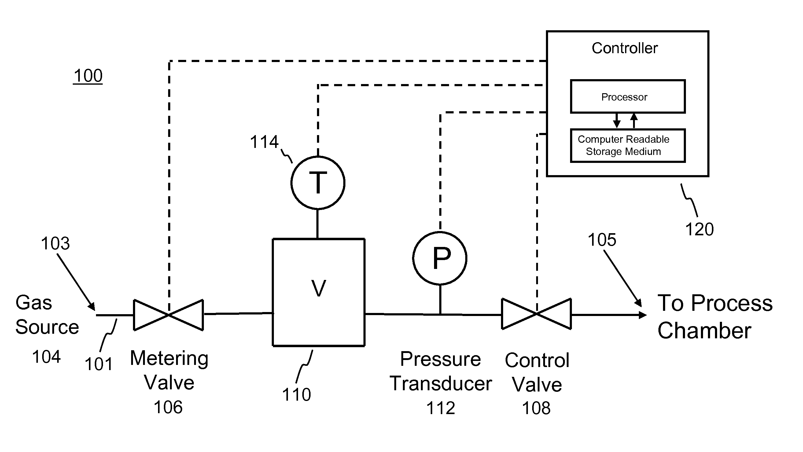
[0037]Embodiments of the present invention provide for a controllable flow restriction in which the dimensions of the flow restriction are measurable and controllable to a very high degree of precision. The measurement and control of the dimensions are precise enough that they can be used to accomplish the self-calibrating gas-flow-control scheme shown in FIG. 1 with the flow accuracy required by the semiconductor industry.

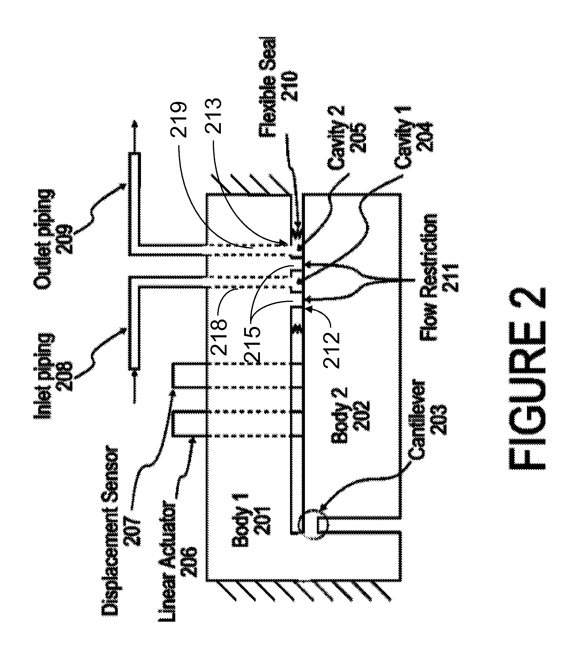
[0038]In various embodiments of the present invention, this level of precision is obtained by incorporating the following characteristics:[0039]1. Uniaxial motion of the two opposing faces of the flow restriction, where transverse and / or rotational motion in the other two axes is limited to less than approximately 1 nm;[0040]2. Measurement of motion in the uniaxial dimension to a precision of approximately 1 nm;[0041]3. Actuation of motion with resolution of approximately 0.1 nm.

[0042]An illustrative embodiment of the invention, shown in FIG. 2, consists of two ad...


PUM


Abstract

A method and apparatus for self-calibrating control of gas flow. The gas flow rate is initially set by controlling, to a high degree of precision, the amount of opening of a flow restriction, where the design of the apparatus containing the flow restriction lends itself to achieving high precision. The gas flow rate is then measured by a pressure rate-of-drop upstream of the flow restriction, and the amount of flow restriction opening is adjusted, if need be, to obtain exactly the desired flow.

Description

RELATED APPLICATION[0001]This application claims priority benefit from U.S. Provisional Patent Application No. 61 / 252,143, filed Oct. 15, 2009, the disclosure of which is incorporated herein by reference in its entirety.BACKGROUND[0002]1. Field[0003]This invention is in the field of fluid flow control and, more specifically the field of high accuracy flow control such as required for, e.g., semiconductor processing, plat panel display fabrication, solar cell fabrication, etc.[0004]2. Related Art[0005]Metering the mass-flow rate of a gas is important to many industrial processes. In the case of the semiconductor industry, metering must be especially accurate, because deviations in the flow rate of only several percent can lead to process failures.[0006]Mass flow is the result of a pressure gradient existing in a system. As long as no external work is done on the system, mass will flow from areas of high pressure to low pressure. This is the working principle in all flow control devic...

Claims


Application Information

Patent Timeline
IPC IPC(8): F15D1/00
CPCG05D7/0635F16K31/004F16K7/14F16K7/16F16K31/006Y10T137/0379Y10T137/0396Y10T137/7737Y10T137/7759Y10T137/7761Y10T137/8158Y10T137/8242Y10T137/8275
Inventor MONKOWSKI, ADAM J.CHALMERS, JAMES MACALLENCHEN, JIALINGDING, TAOMONKOWSKI, JOSEPH R.
Owner PIVOTAL SYST CORP
Learn More