
Method and system for coupling radiation

a coupling radiation and radiation method technology, applied in the field of radiation coupling, can solve the problems of lower coupling efficiency and high optical bandwidth, and achieve the effect of reducing coupling efficiency and increasing optical bandwidth for coupling radiation

Active Publication Date: 2011-05-05
INTERUNIVERSITAIR MICRO ELECTRONICS CENT (IMEC VZW) +1
View PDF17 Cites 21 Cited by
  • Summary
  • Abstract
  • Description
  • Claims
  • Application Information

AI Technical Summary

Benefits of technology

[0005]It is an object of the present invention to provide efficient systems and methods for coupling radiation between two optical elements. It is an advantage of embodiments according to the present invention that an increased optical bandwidth for coupling radiation can be obtained without significantly reducing the coupling efficiency.
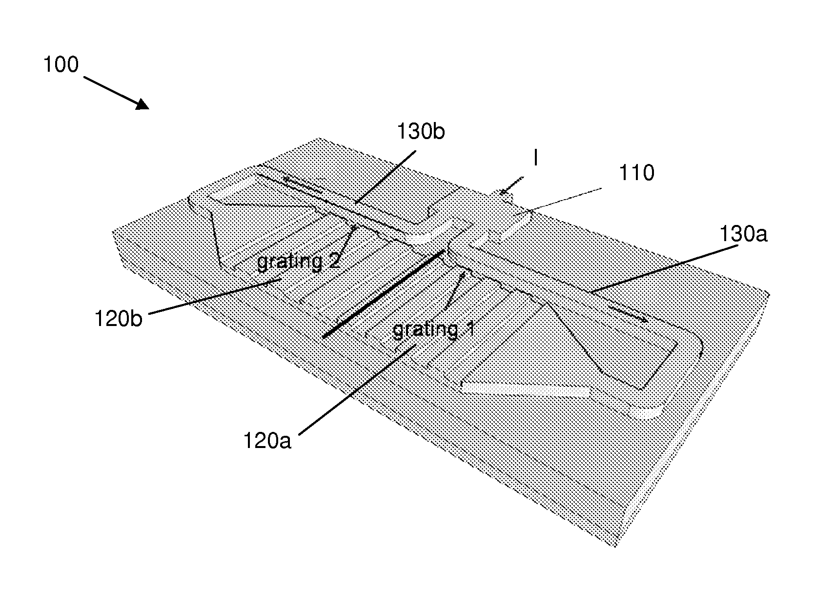
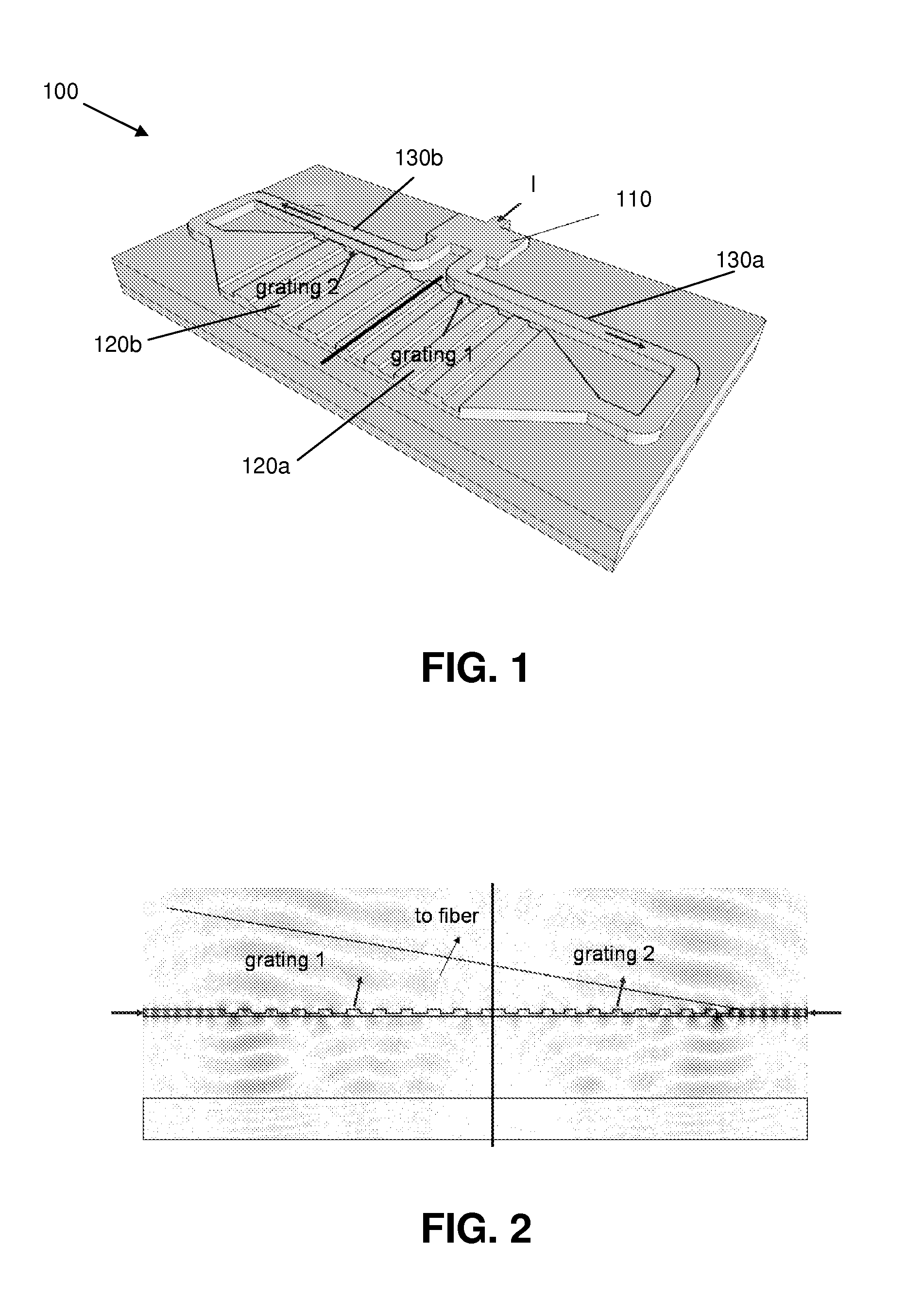
[0007]The present invention relates to a coupler for coupling radiation to one optical element, the coupler comprising a splitter for splitting a received radiation beam in at least two radiation sub-beams, at least two distinct sub-gratings adapted for directing radiation sub-beams such that all radiation is coupled out by the coupler into substantially one direction, and means for guiding each of the radiation sub-beams between the splitter and distinct sub-gratings. It is an advantage of embodiments according to the present invention that an increased bandwidth without significant reduction of coupling efficiency can be obtained using a combination of conventional components, resulting in a coupler that can be easily made.
[0014]A grating strength of the coupler may be adapted such that substantially no leakage between sub-gratings occurs.
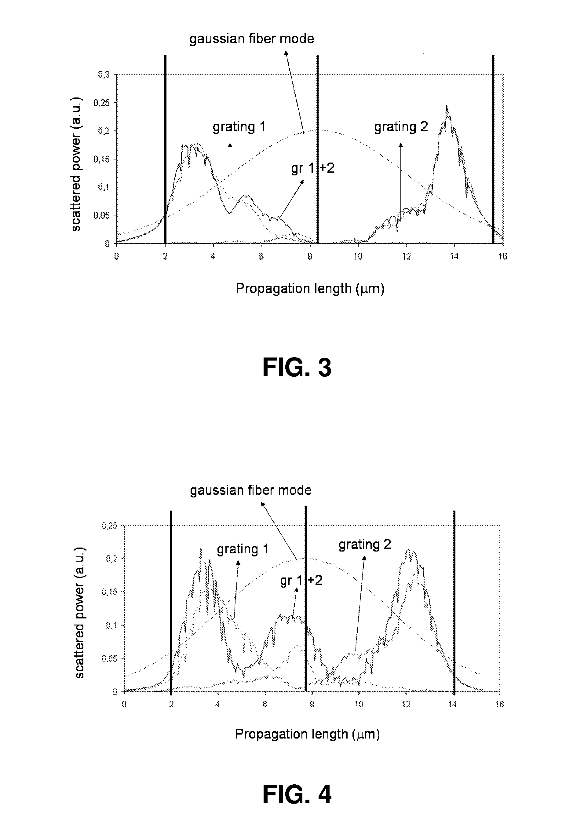
[0016]Apodization of at least one of the sub-gratings may be performed for maximizing the overlap with a Gaussian fiber mode for an optical fiber in optical communication with the coupler.

Problems solved by technology

Decreasing the number of periods will thus result in higher optical bandwidth but lower coupling efficiency.

Method used


Image

  • Method and system for coupling radiation
  • Method and system for coupling radiation
  • Method and system for coupling radiation

Examples


Embodiment Construction

[0033]In the following detailed description, numerous specific details are set forth in order to provide a thorough understanding of the invention and how it may be practiced in particular embodiments. However it will be understood that the present invention may be practiced without these specific details. In other instances, well-known methods, procedures and techniques have not been described in detail, so as not to obscure the present invention. While the present invention will be described with respect to particular embodiments and with reference to certain drawings, the reference is not limited hereto.

[0034]Furthermore, the terms first, second and the like in the description and in the claims, are used for distinguishing between similar elements and not necessarily for describing a sequence, either temporally, spatially, in ranking or in any other manner. It is to be understood that the terms so used are interchangeable under appropriate circumstances and that the embodiments o...


PUM


Abstract

The present invention relates to a coupler (100) for coupling radiation to one optical element. The coupler (100) comprises a splitter (110) for splitting a received radiation beam in at least two radiation sub-beams, at least two distinct sub-gratings (120a, 120b) adapted for directing radiation sub-beams such that all radiation is coupled out by the coupler into substantially one direction, and a means for guiding (130a, 130b) each of the radiation sub-beams between the splitter and a sub-grating (120a, 120b).

Description

FIELD OF THE INVENTION[0001]The present invention relates to the field of radiation coupling. More particularly, the present invention relates to methods and systems for efficiently coupling broadband radiation signals.BACKGROUND OF THE INVENTION[0002]Transferring radiation between a fiber and a second optical element, e.g. an optical circuit often is done by a grating coupler. In order to optimize the functionality of an optical system, one strives for a coupling efficiency that is as high as possible. The coupling efficiency of a grating coupler (e.g. to a fiber) is determined by the amount of power scattered by the grating and the overlap between the Gaussian fiber mode and the scattered power profile by the grating e.g. an exponentially decaying profile for a uniform grating.[0003]The parameters such as e.g. etch depth, filling factor, number of periods N of standard grating couplers can be optimized in order to match the optimum for both criteria. This exercise results in an op...

Claims


Application Information

Patent Timeline
Patent Type & Authority Applications(United States)
IPC IPC(8): G02B6/34
CPCG02B6/125G02B2006/1215G02B6/34G02B6/30
Inventor BAETS, ROELVERMEULEN, DIEDRIKDELBEKE, DANAEHALLYNCK, ELEWOUT
Owner INTERUNIVERSITAIR MICRO ELECTRONICS CENT (IMEC VZW)
Learn More