
Input unit of portable terminal, portable terminal using the same, and operation method thereof

a portable terminal and input unit technology, applied in the field of portable terminals, can solve the problem of significantly lacking ports of the controller, and achieve the effect of reducing the number of ports allotted

Inactive Publication Date: 2011-05-05
SAMSUNG ELECTRONICS CO LTD
View PDF4 Cites 4 Cited by
  • Summary
  • Abstract
  • Description
  • Claims
  • Application Information

AI Technical Summary

Benefits of technology

[0009]In a portable terminal, a portable terminal using the same and an operation thereof according to an embodiment of the present invention, the present invention may discriminate input signals allotted to respective keys while reducing the number of ports allotted to a key pad.

Problems solved by technology

However, since the number of ports of the controller is restrictive, when a number of ports are allotted to the key pad, there is a need for an additional configuration for extension of ports.
Because additional modules require allotment of specific ports of a controller, as time goes by, ports of the controller is significantly lack.

Method used


Image

  • Input unit of portable terminal, portable terminal using the same, and operation method thereof
  • Input unit of portable terminal, portable terminal using the same, and operation method thereof
  • Input unit of portable terminal, portable terminal using the same, and operation method thereof

Examples


first embodiment

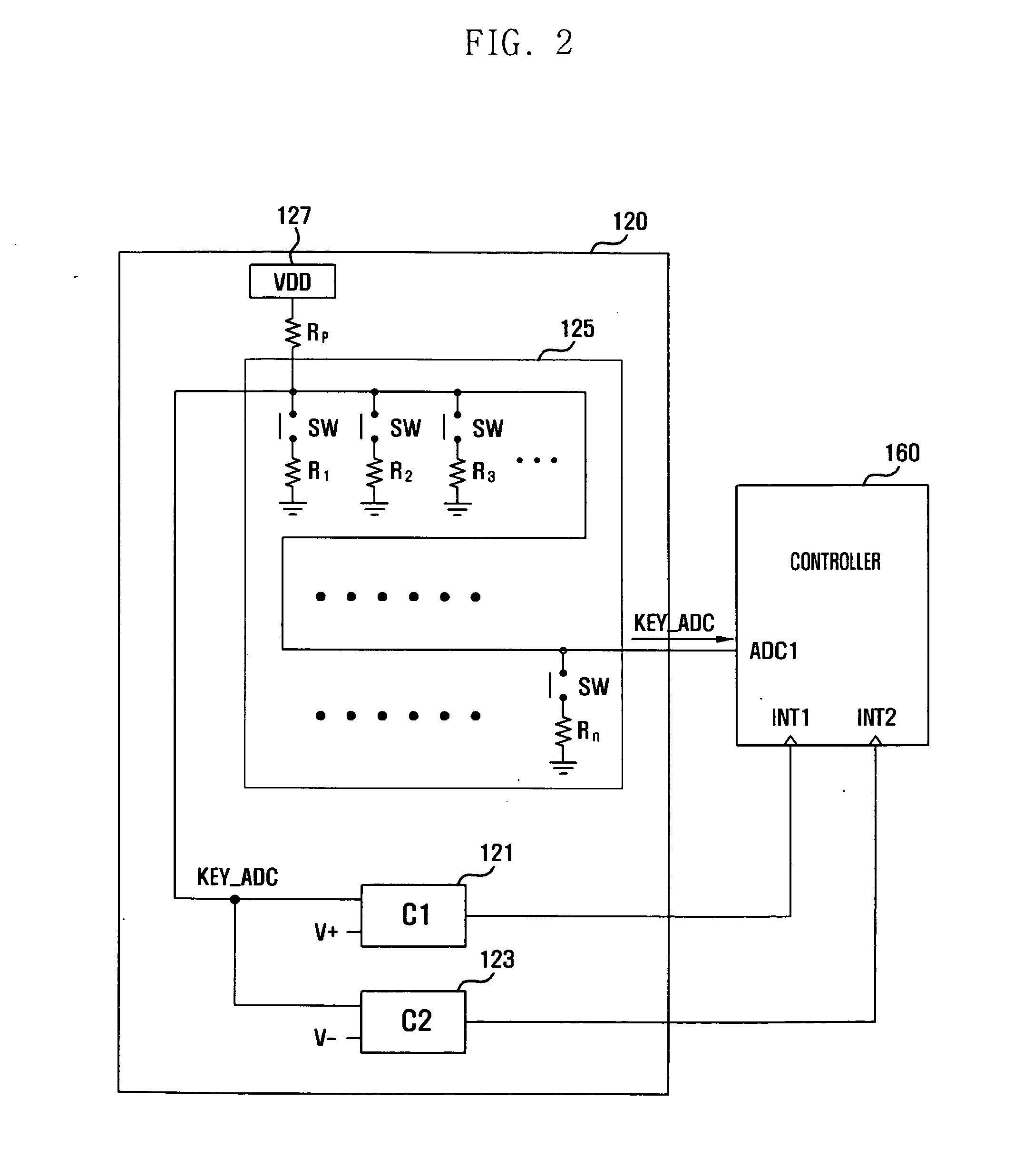
[0031]FIG. 2 illustrates configurations of the input unit 120 and the controller 160 of the portable terminal according to the present invention.

[0032]Referring to FIG. 2, the input unit 120 can include a key row 125 in which a plurality of resistors R1 to Rn are connected to each other in parallel based on switches SW; a first comparator 121 and a second comparator 123 connecting with the key row 125; a reference voltage unit 127; and a reference resistor RP dividing a reference voltage VDD supplied from the reference voltage unit 127. The controller 160 can include an input signal port ADC1 connected to the key row 125, a first comparator port INT1 connected to the first comparator 121, and a second comparator port INT2 connected to the second comparator 123. In this case, the controller 160 can also include ports for signal transmission and reception with other configurations of the portable terminal 100, namely, the RF unit 110, the audio processing unit 130, and the display uni...

second embodiment

[0051]FIG. 3 illustrates configurations of the input unit 120 and the controller 160 of the portable terminal according to the present invention.

[0052]Referring to FIG. 3, the input unit 120 according to a second embodiment of the present invention includes a key row 125 with a plurality of sub-key rows 210, 220, 230, 240, and 250; a reference voltage unit 127 supplying a reference voltage VDD to the sub-key rows 210, 220, 230, 240, and 250; a reference resistor RP disposed between the reference voltage unit 127 and sub-key rows 210, 220, 230, 240, and 250; and a first comparator 121 and a second comparator 123 connected at a contact point between the reference resistor RP and the sub-key rows 210, 220, 230, 240, and 250. The controller 160 may include an input signal port ADC1 connected to the sub-key rows 210, 220, 230, 240, and 250; a first comparator port INT1 connected to the first comparator 121; and a second comparator port INT2 connected to the second comparator 123. The con...


PUM


Abstract

A portable terminal includes: a key row including a reference resistor, switches separately connected to the reference resistor, and a plurality of resistors connected to the switches, respectively; a reference voltage unit connected to the reference resistor and providing a reference voltage; and a first comparator and a second comparator dividing the reference voltage from the reference voltage unit by the reference resistor and at least one resistor connected to an activated switch, and receiving an analog key input signal corresponding to the divided reference voltage.

Description

CROSS-REFERENCE TO RELATED APPLICATION(S) AND CLAIM OF PRIORITY[0001]The present application is related to and claims the benefit of priority under 35 U.S.C. §119(a) to a Korean patent application filed in the Korean Intellectual Property Office on Nov. 3, 2009, and assigned Serial No. 10-2009-0105521, the entire disclosure of which is hereby incorporated by reference.TECHNICAL FIELD OF THE INVENTION[0002]The present invention relates to a portable terminal, and more particularly, to an input unit of a portable terminal discriminating an input signal using an analog digital converter (ADC) and a comparator, and a portable terminal using the same, and an operation thereof.BACKGROUND OF THE INVENTION[0003]A portable terminal is a terminal supporting a call function based on mobility, which has been used in very wide fields due to convenient utility and easy portability. The portable terminal provides various input schemes for providing a user function.[0004]In particular, a convention...

Claims


Application Information

Patent Timeline
Patent Type & Authority Applications(United States)
IPC IPC(8): H03K5/22
CPCH03M11/24H03K5/1534H04B1/40H04M1/23
Inventor LEE, MIN HYOUNG
Owner SAMSUNG ELECTRONICS CO LTD
Learn More