Securing mechanism and electronic device enclosure using the same

a technology of electronic devices and locking mechanisms, which is applied in the direction of washstands, lighting support devices, instruments, etc., can solve the problems of plurality of screws in the installation and removal of components, and achieve the effect of avoiding the plurality of screws

Inactive Publication Date: 2011-05-05
HONG FU JIN PRECISION IND (SHENZHEN) CO LTD +1
View PDF17 Cites 2 Cited by
  • Summary
  • Abstract
  • Description
  • Claims
  • Application Information

AI Technical Summary

Problems solved by technology

However, installation and removal of the component are inconvenienced by

Method used


Image

  • Securing mechanism and electronic device enclosure using the same
  • Securing mechanism and electronic device enclosure using the same
  • Securing mechanism and electronic device enclosure using the same

Examples


Embodiment Construction

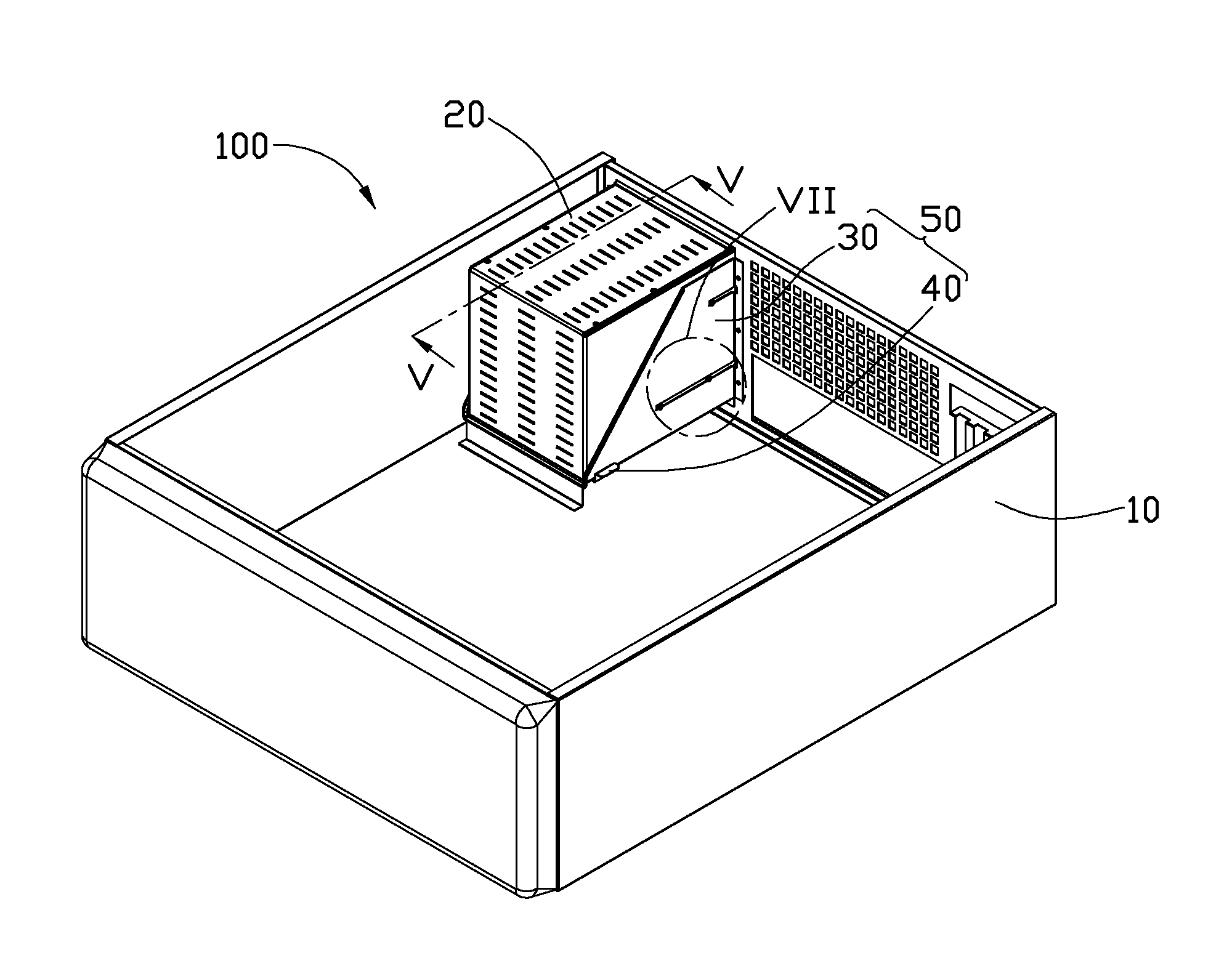
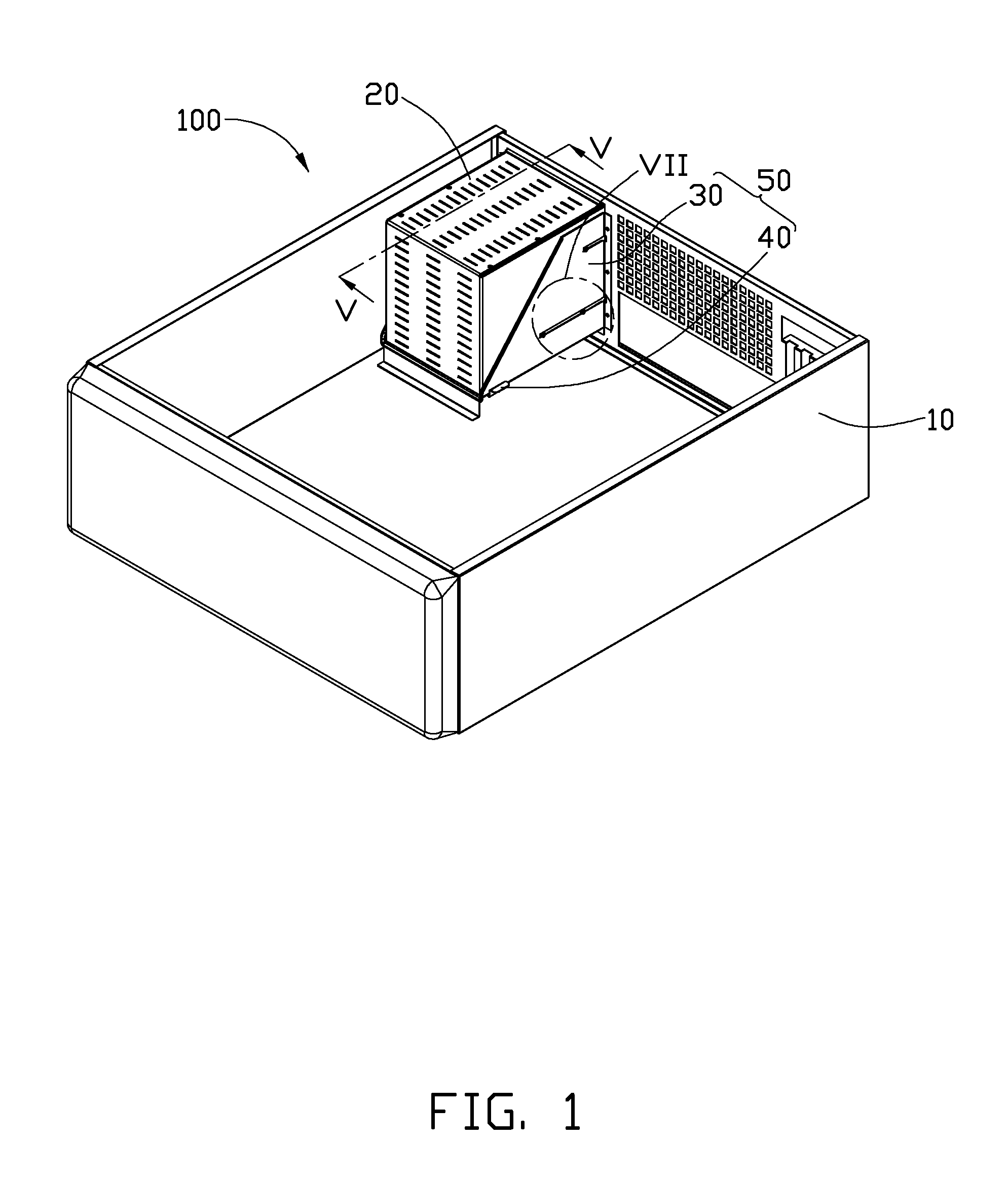
[0015]Referring to FIG. 1, an embodiment of an electronic device enclosure 100 includes a housing 10, and a securing mechanism 50 fixed in the housing 10 to secure a component 20 inside the housing 10. The securing mechanism 50 includes a fixing bracket 30 fixed on a sidewall of the housing 10, and a resilient member 40 fixed on the fixing bracket 30. In the illustrated embodiment, the component 20 is a power supply. Alternatively, the component 20 may be a hard disk, a compact disc drive, or other component.

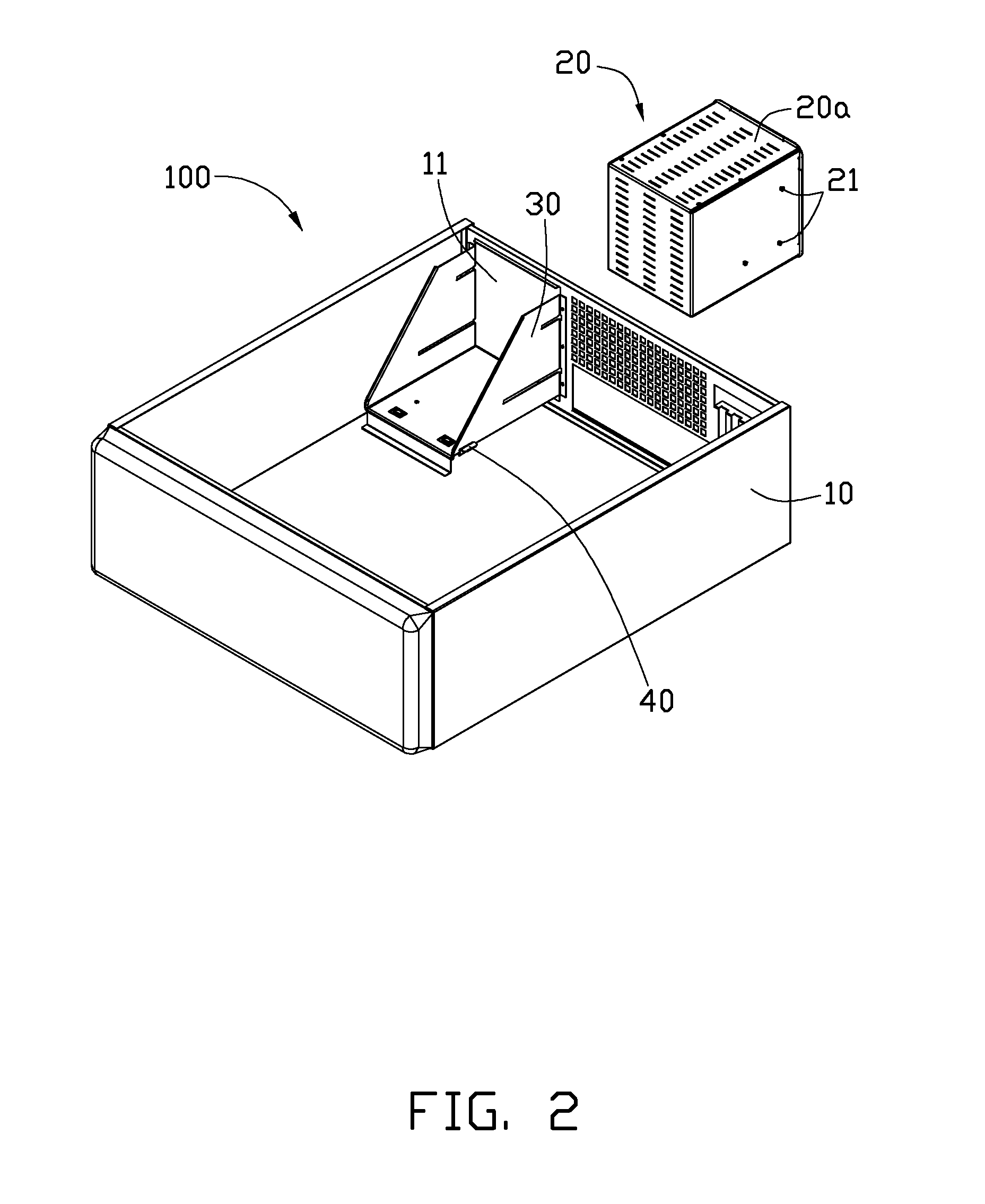
[0016]Referring to FIG. 2, the housing 10 defines an opening 11 in a sidewall. The fixing bracket 30 is fixed in the housing 10 adjacent to the opening 11, thus the component 20 can be positioned onto the fixing bracket 30 through the opening 11.

[0017]The component 20 includes a component chassis 20a. The component chassis 20a includes a plurality of positioning portions 21 and a plurality of engaging portions 23 (shown in FIG. 6) positioned on the component chassis 20a. In the ...


PUM


Abstract

A securing mechanism secures a component in an electronic device enclosure. The component chassis includes a positioning portion and an engaging portion positioned on the component chassis. The securing mechanism includes a fixing bracket and a resilient member fixed on the fixing bracket. The fixing bracket includes a guiding portion latching with the positioning portion to enable the component to slide relative to the fixing bracket. The resilient member includes a latching portion engaged with the engaging portion to assemble the component on the fixing bracket. When the resilient member deforms resiliently, the latching portion disengages from the engaging portion to remove the component from the fixing bracket.

Description

BACKGROUND[0001]1. Technical Field[0002]The present disclosure relates to a securing mechanism and an electronic device enclosure using the securing mechanism.[0003]2. Description of Related Art[0004]Electronic devices, such as desktop computers, notebook computers, and digital video disc players, are popular and widely used. An electronic device generally includes an enclosure securing electronic components therein.[0005]A commonly used electronic device enclosure includes a housing and securing mechanism fixed inside the housing to secure a component. The securing mechanism includes a fixing bracket fixed on a sidewall of the housing, two slide bars formed on opposite sides of the component, and a plurality of screws. The fixing bracket forms two sliding rails corresponding to the slide bars. The slide bars slide on the sliding rails to a desired position, and are then fixed on the sliding rails by using the plurality of screws, thus the component is secured in the housing. Howeve...

Claims


Application Information

Patent Timeline
IPC IPC(8): A47B81/00A47B96/06
CPCG06F1/183
Inventor TANG, ZI-MING
Owner HONG FU JIN PRECISION IND (SHENZHEN) CO LTD
Why Eureka
Try Eureka